Building a World-Class Cascoded Balanced XF5 on a Budget
As I've explained in my Ultimate F5 thread, one of the amps I was interested in was the Balanced XF5. The XF5 circuit was finalized and first built by EUVL. When I tried to modify the design and carry it forward, I was never clear on the answers provided in my original thread and was initially quite hesitant to build the amp. Having hit a wall on many design issues, I thought I might not proceed. Luckily, Nelson Pass added some hints which answered my questions and I was off and running. One of his hints was about cascoding the XF5. Never one to pass up on a great hint, I added a cascode to the circuit.
I am a value driven person. I don't mind spending a lot of money - if I know I'm getting good value. You'll see this theme repeat itself time and again in this build. I view the amplifier outlined below as a great value.
My build has the following features:
· 12v - 800VA Antek toroid (capable of 1000VA)
· Matched Toshiba 2SK1530/2SJ201 outputs - 4 pairs from ZhouFang
· Matched JFETs (2SK170BL and 2SJ74BL - with differential match for degeneration)
· Two Conrad MF35-151.5 Heat Sinks
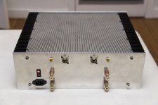
· Custom case with 1/2 inch Aluminum faceplate, balanced and RCA inputs
· Fukushima resistors
· 8*MSRF1560 Ultrasoft diodes
· Custom PCBs
· Power Supply - CRC (in the style of the F5 Power Supply). Currently 8x18000uF, will be 4x 68000uF when I upgrade the case
My goal is to give anyone interested building this amp the benefit of my trial and error.
Let’s go section by section:
Power Supply
The quick summary is I used a CRC Power Supply as NP outlined in his F5 Manual.
· In current configuration, I use the exact layout NP shows except I used 18,000uF 50V caps sourced from Apex Jr. for $20 total.
· I use four 3W, 0R47 Panasonic resistors for the “R” and I kept the 3W 2.2K bleeder resistors NP shows.
· I changed the NTC connected to the ground to 20 ohm 8A beast (MS32 20008 from Ametherm), and I think I’m going to change the two NTCs connected to the 110V side from the 10 ohm 5A (SL18 10005 currently used) to the 20 ohm 8A version (MS32 20008). The 5A pieces get a little too hot for my taste.
My cost for the CRC filter was $26. I used a commercial PCB (I was tight on time) which added $14 to the cost for a total of $40. I would solder point to point in the future, or etch a Power Supply PCB.
I bought an 800VA, 12V toroid from Antek (Model AN-8412) for $95 including shipping! The toroid is rated to 1000VA, so I had a fair bit of leeway. I considered dual 500VA toroids (Antek AN-5412), but the case I had would not easily fit two toroids. The added cost of going dual mono would be $70.
Antek is great, I highly recommend them. The 800VA version has 4 sets of outputs, I only wanted two. The solution is pairing the sets. In speaking to Jon at Antek, the first two pairs can put together to form one set, as can the last two pairs. The result is two output sets instead of four.
Total cost of Power Supply = $135 as it stands
Total cost of Dual mono = $205 (two sets of caps and two 500VA toroids)
Matched Toshiba Outputs
I bought 4 pair of N-P matched Toshiba 2SK1530/2SJ201 outputs from forum member ZhouFang. I paid $114 for the set.
I am waiting for Toshiba 2SK3497/2SJ618 to arrive. I suspect they’ll surpass the 2SK1530/2SJ201 sets at a fraction of the cost ($40 a set). I’ll keep everyone posted on how they sound when they arrive (in transit now).
Matched JFETs
I bought a gob of unmatched JFETs and matched my set myself. I doubt most have the disposition to go down this path. I’d recommend buying a set to your specs from a forum member. I have a few extra sets I might sell, but I do not want to make a business of it. I estimated cost of buying these from a forum member at $40. The Idss matching is a bit more complex than usual if you want to do the degeneration trick described by EUVL (as I did). From the DIYAudio forum:
“If you use the 5R degeneration on the 2SJ74, as I recommended, then you can calculate the Idss of the 2SJ74's using the following equation :
Idss (2SJ74) = Id * (1 + Rs.Yfs)
where Id = Idss of the 2SK170 in this case; Rs =5.1R; Yfs = 0.033 S for 2SJ74 at that bias range.”
In essence, if you use 10R resistor for the 2SK170 and a 15R1 resistor for the 2SJ74 your 2SJ74 Idss = (Id of your 2SK170) +(Id of your 2SK170) *0.1683
By way of example: In the case of an Idss of 7mA for a 2SK170, you’d use a 2SJ74 with an Idss of ~8.18mA. There’s a bit more to the details if you use an Idss of the 2SK170 in a different range, but the equation is a good approximation of what is needed this “trick”.
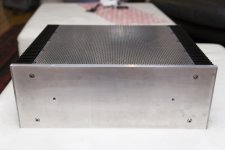
Conrad Heat Sinks with Custom Aluminum Case
Here’s a place that is a real stopping point for many DIYers, I know it was from me. I live in the center of Manhattan, the idea of having a mill or a lathe is beyond fantasy. Even finding someone with machining equipment is out of the question. As such, I embarked on finding a case. I found one in the forum and I’m still waiting for the case supplier to PM me back as to his availability for case building for others. He’s a great guy, but he can get extremely backlogged.
Total cost is in the $250-300 range depending on the specifics of what you want.
One issue I faced was I had spec’ed the case for a stock F5. I pressed the case into service when I made the Balanced Cascoded F5. As such, some of the layout internally was not ideal. The toroid for the Cascoded Balanced F5 is larger than the stock F5, thus it was close to the input/output area on the back of the case than I wanted. The PCBs for the new circuit are larger than the stock circuit; they had to be placed in a compromised position. While I think I can make the current case work well, I’ll likely use it as a test bed case and make a new one from scratch for the new configuration.
Fukushima Resistors
Ah yes, the Fukushima model MPC74 in values of 0R22 and 0R18. These are 5W really nice, non-inductive, metal band resistors from Japan. They are royally hard to get in the USA, I suspect they just got a lot harder with the recent earthquake in Japan. If you’re dead set on these, try to join a group buy, in bulk they’re about $1 each. You can also deal with Buerklinin Germany.
On the other hand, there are many excellent resistors by Caddock and Vishay that can fit the bill here. I’ll leave it to you whether the Fukushima are worth the hassle.
Expected cost of eight ~$8.
MSRF1560 Ultrasoft diodes
In reality, any diode bridge that can support the current draw will work. I went with ultrasofts just to try them. They seem really great, but I don’t know that I could tell the difference if I had to. I was going to use MUR3020s, but the MSRF1560s can be bought with a fully plastic case. That case allows for direct mounting to the heat sink without any pads or goop – they’re just easy.
Total cost ~$16.
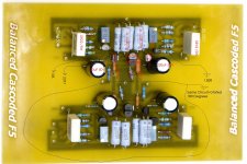
Custom PCBs
I already posted a blog on my DIYAudio blog space on how I etch my PCBs. I am attaching the files needed to etch and stuff the PCBs to this posting. Please note, Juma was kind enough to send me his F5 layout, I was able to modify it in “MS Paint” to get where I needed to go. Since I made this layout, I’ve mastered a free PCB layout program, but this layout attached was done the “old school” way. Also attached is a picture with all the components labeled to help with stuffing, and a hand touched up schematic based on the original schematic.
I'm sure there will be some questions about the layout, I did my best with the picture, let me know how I can help.
At some point, I’ll re-do the PCBs with traditional PCB layout software.
My cost for the PCBs was quite modest, but for someone starting from scratch, assume about $20.
Conclusion
If you follow this post, you may spend:
Case $250
Power Supply (Single) $135
Power Supply (Dual mono) $205
Output MOSFETs $114
JFETs $40
Resistors $16
Diodes $14
PCBs $20
Total (Single PS) $589
Total (Dual mono PS) $659
As I mentioned in another post, if you have a case around, the price drops by $250. Also, I suspect the Toshiba 2SK3497/2SJ618 which are in transit will work really well, and the price will drop another ~$80. With an old case, and the new Toshibas, you might make this build for $259!
I'm sure I've left out some useful information. I'm happy to help either in this thread or by PM. I don't check the forum everyday, so please have some patience with my response time.
Happy listening!
Attachments
Last edited:
Pictures
I forgot to post pictures (I posted them in the other threads , but this may have different readership). In case you haven't seen these before, below are pictures of the current Cascoded Balanced XF5.
I forgot to post pictures (I posted them in the other threads , but this may have different readership). In case you haven't seen these before, below are pictures of the current Cascoded Balanced XF5.
Attachments
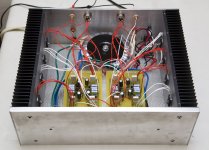
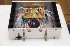

one thing i'm wondering, where is the psu/caps in your case?
qusp--looks as though the amp pcbs are "elevated" on the chassis, with the psu and caps underneath. The routing of the transfo secondary leads (green and blue) also suggest that.
Ken
one thing i'm wondering, where is the psu/caps in your case?
They're under the PCBs for the channels.
qusp--looks as though the amp pcbs are "elevated" on the chassis, with the psu and caps underneath. The routing of the transfo secondary leads (green and blue) also suggest that.
Ken
I'll take more pics and post tonight. I'll try to show more detail on the PS.

i'll hazard a guess, given the thread title and say building it at 1/3 of the cost was a motivator.
wrt 12v supply i'm interested in as well, was it to allow playing with really high bias and more outputs without changing the heatsink NYCone? because i considered lower vcc than normal also for the same reasons and i agree with Luke above, mounting to the sinks directly would be better, but you know that so i didnt mention it earlier. i guess there were several compromises in layout taken to save time or money as this build and case was a workhorse to find which you preferred of several topoloigies
wrt 12v supply i'm interested in as well, was it to allow playing with really high bias and more outputs without changing the heatsink NYCone? because i considered lower vcc than normal also for the same reasons and i agree with Luke above, mounting to the sinks directly would be better, but you know that so i didnt mention it earlier. i guess there were several compromises in layout taken to save time or money as this build and case was a workhorse to find which you preferred of several topoloigies
Last edited:
A question.....
What advantages are you expecting with this build and why only a 12v supply?
I used a CRC Filter like NP did in his F5. If you keep the resistor part of the CRC low, you don't need a 15V toroid to get to ~16V rails. The other thread is using 15V toroids and has greater losses of voltage along the way to the rails. Think about it - 12V * 1.41 = 16.92V. I measured 15.8V last time I had the DMM out.
Finally, I would have gone for lower rail voltage if I could have found the right toroid - NP shows there's no benefit of the higher voltage for output as long as one is in the linear range of the output devices. ~15.8V gets me to the right place though.
what are the benefits over euvals design and did you consider mounting the board on the sink, ie no leads?
IO may end up that way. This case was not intended for this amp. to keep things easy, I did the point to point to the outputs. I think I'll make small PCBs and jumper the board to the heatsinks like NP does in his BA series (and others). The PCBs posted allow for direct mounting if that's your desire.
i'll hazard a guess, given the thread title and say building it at 1/3 of the cost was a motivator.
wrt 12v supply i'm interested in as well, was it to allow playing with really high bias and more outputs without changing the heatsink NYCone? because i considered lower vcc than normal also for the same reasons and i agree with Luke above, mounting to the sinks directly would be better, but you know that so i didnt mention it earlier. i guess there were several compromises in layout taken to save time or money as this build and case was a workhorse to find which you preferred of several topoloigies
Yes, as long as your outputs are in the linear range, I'd push for higher bias. Thus the 12V toroid. NP suggested 12V rails in my other thread! One can then add outputs if needed to handle the bias.
Finally, I try to build value devices anytime I do a project. Value is the driver here - but without quality compromise. The only issues for me is whether I should re-case the amp (I will), and whether dual mono (an extra $70) is worthwhile. Other than that, I wouldn't change a thing.
Last edited:
cool, i thought as much and i intend to go the same direction, thinking of doing the same with my aleph jx to allow higher bias and i was actually glad to see you had specced 12v as this was the number i was looking at, with the same conrad sinks. so good show mate!
i do have to go dual mono though in both builds, as the rest of my signal path is the same up to the amps, so a heavy shipment of iron from sumR is due soon, more than 70 dollars difference for me though, especially with international shipping taken into account.
there are a couple of decent custom tx providers here too, but the cost of their units works out to the same as richards with shipping, so given my good previous experience with him i'll continue. anything slightly specialized here in oz is a ripoff, so unless warranty support is an issue (not really with toroids) its not worth it.
Let the Games Begin - my 2SK3497/2SJ618 have arrived!
My 20 pair of 2SK3497/2SJ618 arrived. This pair has ~2.5 the Ciss of the 2SK1530/2SJ201 combination at the same voltage! Not only that, but they are less expensive than the 2SK1530/2SJ201.
I am going to have an interesting night!
My 20 pair of 2SK3497/2SJ618 arrived. This pair has ~2.5 the Ciss of the 2SK1530/2SJ201 combination at the same voltage! Not only that, but they are less expensive than the 2SK1530/2SJ201.
I am going to have an interesting night!
I thought that the main reason to cascode the JFETS was to use a higher voltage supply. Any other reasons to use cascoding on a low voltage as you have? Also how are the heat sinks working? Obviously that's why you are keeping the voltage low. as you mentioned, they are about the right size for a regular F-5.
A good thing about the cascoding would be that at any time you could up the voltage if you ever get a case with double the heatsink area!
A good thing about the cascoding would be that at any time you could up the voltage if you ever get a case with double the heatsink area!
- Status
- This old topic is closed. If you want to reopen this topic, contact a moderator using the "Report Post" button.
- Home
- Amplifiers
- Pass Labs
- Building a World-Class Cascoded Balanced XF5 on a Budget