Hello Folks!
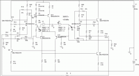
I was toying around some Pspice simulation around the following version of a BJT Aleph X.
Didn't put the mcmillan res.
Don't know if it works properly.
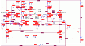
Anyway I'm showing the results. Glad to know what you think.
Thank you.
I was toying around some Pspice simulation around the following version of a BJT Aleph X.
Didn't put the mcmillan res.
Don't know if it works properly.
Anyway I'm showing the results. Glad to know what you think.
Thank you.
Attachments
It's not uncommon to simulate only with a single output pair, but use multiple in the real design. Sure it is not entirely exact concerning stability, but in the end the spice models usually aren't either  Hannes
EDIT: just saw
Well, so beware then.
EDIT: just saw
Don't know if it works properly.
Well, so beware then.
Honestly, I don't see the point of replacing MOSFETs with BJTs. BJTs are older technology, less stable and prone to thermal avalanche. On the other hand, MOSFETs are more modern, very stable and will progressively shutdown when too hot, giving you more safety for your amps and speakers.
But I respect the intellectual exercise....
Yves
But I respect the intellectual exercise....
Yves
I don't see the point of replacing MOSFETs with BJTs
Well, if you want a cool amp they're the better choice if you want lower distortion. Hannes
In my application I am designing a small amp to use on 12v from a spare 145watt computer switching supply.
All I have are a bunch of IRF510's to work with for the moment and can still be found at the local radio shack store should any one want to give it a try ,once I get a working version done.
In my simulations I have found that I can get a lot closer to the 12v rail voltage using a 2N3055 BJT in the CCS (constant current source)in the top half than I can using the FET's.
This also reduces my parts count as well as the PD of the 2N3055 is 115 watts compared to 20 watts of the IRF510.
I know that this is irrelevant using normal practices with a higher power supply voltage and proper higher power FET's.
But I thought that it would be fun to build a smaller version using some junk box parts.
And it would be a low cost way to venture in to the realm of Class A to see what it is all about.
For normal listening with my little Sony bookshelf speakers 18" away on a desktop 20 watts is more than enough and quite loud at those levels, In fact I have never needed them any louder than that.
I have a much larger system when I need to rock out.
jer
In my simulations I have found that I can get a lot closer to the 12v rail voltage using a 2N3055 BJT in the CCS (constant current source)in the top half than I can using the FET's.
You get closer to the rail as BJTs limit rail swing by 1 volt or so (VBE plus little extra) and mosfets eat VGS (3.5 V or so).
Junk box amps are a nice playground! Just keep in mind not to go lower than the 12 V rails as the capacitances in the fets are very non linear below 12-15 V or so.
Hannes
Yes,that was was what I had figured out if I were to use a higher power supply voltage this problem goes away.
I am working on the circuit for use on a 12v pc supply so I needed to get as close to the rail that I can.
My first version uses opamps to drive the output Device,So this compensates for most of the non-linearity's even though it is still operating in class A mode.
I also have a fully transistorized version in mind and that will be the one that I will present here in the Pass-Labs Forum when I get it working.
jer
Don't know if it works properly.
Possibly the current source would work better as a "mu follower" as the Vce
across the little npn transistor which regulates it is low, and you will see some
non-linearity there. ZM or someone here will point you toward such a circuit
if you don't already know it.
- Status
- This old topic is closed. If you want to reopen this topic, contact a moderator using the "Report Post" button.
- Home
- Amplifiers
- Pass Labs
- Aleph X with BJT, anyone?


