Wanted to originally post this as a part of F5 thread, but thought it would be lost in 1000s of posts there.
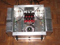
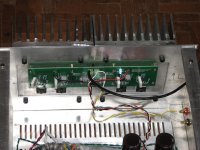
My problem is with a recently built F5 using CViller ver 2.0 boards and running dual output pairs of Toshibas.
The build is stock F5 schematic except the outputs. Even the wiring is as per the original FW F5. This has worked well for my other F5 builds. No problem.
Now I have a slight hum in both the channels of F5 with the input signal shorted. I tried lot of things and finally managed to reduce the hum by nearly half, by soldering two 220uF electrolytics on the F5 PCB across the power rails. But there is STILL hum.
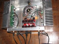
I tried shielding the toroid with a sheet steel barrier, but no difference.
The power supply is a standard Pass PS with 4 * 15000 uF on each rail in a CRC config.
I have tried lifting the ground from the chassis/electrical earth, but no change.
Clearly by adding few caps on the PCB, there is a improvement. What else can be done. Should I add a small nano/pico cap as well along with 220uF? The hum seems to be getting picked up at the PCB location, or through the power rail wiring to the PCB.
Here are the images (before adding the caps at the PCB):
Thanks in advance.
My problem is with a recently built F5 using CViller ver 2.0 boards and running dual output pairs of Toshibas.
The build is stock F5 schematic except the outputs. Even the wiring is as per the original FW F5. This has worked well for my other F5 builds. No problem.
Now I have a slight hum in both the channels of F5 with the input signal shorted. I tried lot of things and finally managed to reduce the hum by nearly half, by soldering two 220uF electrolytics on the F5 PCB across the power rails. But there is STILL hum.
I tried shielding the toroid with a sheet steel barrier, but no difference.
The power supply is a standard Pass PS with 4 * 15000 uF on each rail in a CRC config.
I have tried lifting the ground from the chassis/electrical earth, but no change.
Clearly by adding few caps on the PCB, there is a improvement. What else can be done. Should I add a small nano/pico cap as well along with 220uF? The hum seems to be getting picked up at the PCB location, or through the power rail wiring to the PCB.
Here are the images (before adding the caps at the PCB):
An externally hosted image should be here but it was not working when we last tested it.
An externally hosted image should be here but it was not working when we last tested it.
An externally hosted image should be here but it was not working when we last tested it.
An externally hosted image should be here but it was not working when we last tested it.
An externally hosted image should be here but it was not working when we last tested it.
Thanks in advance.
pictures are dead thumbnails
anyway , few tips without seeing details -you can try to rotate toroid
also - you can try to displace toroid from the box ( extend wires temporary) to be sure that hum isn't magnetically induced
if nothing of that helps , buy some caps
serious ones - 10mF upwards
anyway , few tips without seeing details -you can try to rotate toroid
also - you can try to displace toroid from the box ( extend wires temporary) to be sure that hum isn't magnetically induced
if nothing of that helps , buy some caps
serious ones - 10mF upwards
pictures are dead thumbnails
anyway , few tips without seeing details -you can try to rotate toroid
also - you can try to displace toroid from the box ( extend wires temporary) to be sure that hum isn't magnetically induced
if nothing of that helps , buy some caps
serious ones - 10mF upwards
Sorry. Will post the pictures again.
Have tried turning the toroid. No difference. Have not tried removing the toroid out of the box. When you say 10 mF, you mean 100000 microfarad isn't it?
Last edited:
First question -- when you short the inputs, does it still hum?
Second -- I would route the input cable along the side of the chassis and away from the filter caps. Consider using shielded twisted pair, not coax, and connect the shield on the amplifier side.
Third -- You might want to consider a ground loop breaker if the above don't work.
Second -- I would route the input cable along the side of the chassis and away from the filter caps. Consider using shielded twisted pair, not coax, and connect the shield on the amplifier side.
Third -- You might want to consider a ground loop breaker if the above don't work.
First question -- when you short the inputs, does it still hum?
Second -- I would route the input cable along the side of the chassis and away from the filter caps. Consider using shielded twisted pair, not coax, and connect the shield on the amplifier side.
Third -- You might want to consider a ground loop breaker if the above don't work.
Ok. Will change the input wire from coax to twisted pair with a shield.
I have heard about ground loop breaker but do not know what it is exactly.
Is that 8 mosFETs attached to those heatsinks?
How many F5s are in there.
+-60mF should get ripple low enough?
Turn the bias down to 100mA. Does it still hum?
How much hum, measure it?
It is almost certainly a wiring fault.
Andrew, this is a dual output pair per channel. Therefore there are 4 mosfets on each channel.
Will check with 100mA of bias. I cannot see any wiring fault. I have made couple of F5s before with the same wiring topology and they are dead silent.
Thanks.
Is that 8 mosFETs attached to those heatsinks?
How many F5s are in there.
+-60mF should get ripple low enough?
Turn the bias down to 100mA. Does it still hum?
How much hum, measure it?
It is almost certainly a wiring fault.
How do I measure hum? Ac at the output?
Thanks. Will try the rewiring.Anilva
maybe you have a bunch of wires running to close and parallel to each other.
Could you trim the excess off and keep suply output and imput avay from eah other and crossing at 90.
If you draw twice as much current as standard F5 you need more filtering caps.
I did not think on these lines at all. Makes sense.
Third -- You might want to consider a ground loop breaker if the above don't work.
what is this? Is this 'ground lift switch', in which case I tried and failed.
If you draw twice as much current as standard F5 you need more filtering caps.
If you have, or can borrow a 'scope, I'd look for ripple on your power supply rails (look for AC voltage on the DC rails). If this is the problem, additional filter caps (double what you currently have) can help solve.
In addition, is your transformer sized properly for this amp design? Suitable VA capacity?
Well, I dont have access to a scope. I will try with increased filter cap size.
The toroid is rated at 600VA. Runs quietly. No problem. Supply rails are at 22.7 VDC on load.
Far easier to reduce output bias to make the amp into a normal ClassAB. Then the Hum will be measurable or not.
You can measure the hum on the output.
You can measure the Ripple (almost=Hum) on each supply rail.
Do this with high bias and with low bias.
Once we have those numbers we can estimate whether the capacitors are too small, or are damaged, or are empty cans.
You can measure the hum on the output.
You can measure the Ripple (almost=Hum) on each supply rail.
Do this with high bias and with low bias.
Once we have those numbers we can estimate whether the capacitors are too small, or are damaged, or are empty cans.
- Status
- This old topic is closed. If you want to reopen this topic, contact a moderator using the "Report Post" button.
- Home
- Amplifiers
- Pass Labs
- Unable to fix hum on my F5