Do you have Thermistors soldered on place "HL" on capacitor board, and did you groung this GND trace to the right point ?
Yes. The point is grounded to Chassis and also Power Earth, as per Papa's PS schematic.
Update on hum removal efforts
I got a chance to try around with a few things to remove the small amount of AC hum coming out of the speakers (when I place my ear close to the speaker).
Firstly I measured the AC hum at the output. It measures 7mV with input open and ~4mV with input shorted.
I tried turning the toroid 90 degrees, reversing the AC leads to the bridge rectifier, rerouting the wires. No big difference. Faint hum still exists and the hum levels measure 3.5mV at the output.
I reduced the bias to 100mV on R11/R12 to see if the capacitance I have on the PSU is the cause. Hum levels are much much lower, but not gone yet.
Hence I am unable to put my finger on what is causing the hum. I will upgrade the caps and check.
Is your PSU Zero Volts separate from your Main Audio Ground?
Turning down the bias reduces the mains ripple on the PSU. The F5 produces less Hum as a result.
It is either PSRR letting excessive ripple through to the output or supply rail ripple modulation that is radiating into the low level circuits.
or
something else.
A target for a hum free system is <0.1mVac at the output. A lesser target is <=0.6mVac at the output. This should just about be inaudible with medium sensitivity speakers.
See posts 13 and 15......
When you tested by decreasing your bias, you reduced the current flow thru your MOSFETs. That, in turn, reduces the load on your power supply, which effectively reduces your power supply ripple--and thereby reduces your hum. Your testing suggests you are close to finding the cause.
If you have additional caps of similar mfd and voltage ratings, do a test--temporarily wire them into your power supply, to increase your filter's capacitance. If the hum is reduced/eliminated, add those caps to your final construction. (As noted in the earlier posts (13 and 15), may be prudent to roughly double the total capacitance of your cap banks.
Another troubleshooting option:
1. Select the one channel with the most hum
2. Disconnect the OTHER channel from your PSU rails
3. Doing so will reduce the load on your PSU (to about half). This in turn would reduce the PSU ripple voltage accordingly.
4. Listen to the one channel that remains connected. If the hum is reduced in this channel, then I'd focus on your PSU capacitance.
5. If no difference (step 4) I'd look further for potential ground loops.
I think I already posted this somewhere else but try this (note I am not familiar with cvillers board)
1) Remove the ground wire(s) from the two boards altogether.
2) attached the ground connection from the board to the RCA ground that is inside your shielded input wire.
3) do NOT connect the shield of the input wire at the board.
4) connect the shield at the input RCA ground side.
5) connect the L and R RCA ground together. (at the inputs/binding post)
6) connect a wire at mid point of the L and R RCA wire to the PS ground.
That should eliminate hum. It did on mine.
Last edited:
Is your PSU Zero Volts separate from your Main Audio Ground?
Turning down the bias reduces the mains ripple on the PSU. The F5 produces less Hum as a result.
It is either PSRR letting excessive ripple through to the output or supply rail ripple modulation that is radiating into the low level circuits.
or
something else.
A target for a hum free system is <0.1mVac at the output. A lesser target is <=0.6mVac at the output. This should just about be inaudible with medium sensitivity speakers.
Andrew, thanks. In the Cvillers board, the audio ground and '0' V are connected together. The board draws the 0V from the PSU PCB, which is a standard Papa design. The 0V at PSU PCB is taken to the chassis ground through a 10ohms thermistor as per Papa's design. Pretty much standard connections like in a FW F5.
The input wires are simple thin multistrand ones, twisted together and connected from RCA inputs to the F5 PCB. No shielding. Earlier used coax cable and created a racket as well. Now I am thinking of buying a twisted pair shielded cable and try.
See posts 13 and 15......
When you tested by decreasing your bias, you reduced the current flow thru your MOSFETs. That, in turn, reduces the load on your power supply, which effectively reduces your power supply ripple--and thereby reduces your hum. Your testing suggests you are close to finding the cause.
If you have additional caps of similar mfd and voltage ratings, do a test--temporarily wire them into your power supply, to increase your filter's capacitance. If the hum is reduced/eliminated, add those caps to your final construction. (As noted in the earlier posts (13 and 15), may be prudent to roughly double the total capacitance of your cap banks.
CanAm Man, thanks. I do not have additional capacitors for testing. I have ordered them and once they reach me, will test with additional capacitance. I will test with one channel and see meanwhile.
I think I already posted this somewhere else but try this (note I am not familiar with cvillers board)
1) Remove the ground wire(s) from the two boards altogether.
2) attached the ground connection from the board to the RCA ground that is inside your shielded input wire.
3) do NOT connect the shield of the input wire at the board.
4) connect the shield at the input RCA ground side.
5) connect the L and R RCA ground together. (at the inputs/binding post)
6) connect a wire at mid point of the L and R RCA wire to the PS ground.
That should eliminate hum. It did on mine.
I am confused a bit. Going by your suggestion, there seems to be a loop created with the shielded wire isn't it? Can you point out to your earlier post tha you are referring to?
Cheers.
Well since you just said that the input RCA wires are not shielded, that won't be a problem.
Basically what I did was allow any noise that the may be amplified to run away from the amp board.
Right now, what you have is any noise that the RCA picks up, go towards the amp and flows from the amp board to PS ground.
Which will lend it being amplified.
The way I did it was to have any noise that may be picked up, flow away from the amp, and have it grounded closer to the RCA posts. Thus the grounding to the PS ground between the RCA's
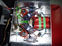
In the pic I have the circled my grounding scheme. The black wire to the amp board has the signal, ground, and shield. The signal is obviously connected at both ends, the ground is connected at both ends, but the shield is connected only at the RCA ground. The white wire connects the L and R RCA ground. I should have connected the white wire going to the PS ground in the middle, but that is for later mod.
Anyways please ignore the mess in there. new caps on the way.
Basically what I did was allow any noise that the may be amplified to run away from the amp board.
Right now, what you have is any noise that the RCA picks up, go towards the amp and flows from the amp board to PS ground.
Which will lend it being amplified.
The way I did it was to have any noise that may be picked up, flow away from the amp, and have it grounded closer to the RCA posts. Thus the grounding to the PS ground between the RCA's
In the pic I have the circled my grounding scheme. The black wire to the amp board has the signal, ground, and shield. The signal is obviously connected at both ends, the ground is connected at both ends, but the shield is connected only at the RCA ground. The white wire connects the L and R RCA ground. I should have connected the white wire going to the PS ground in the middle, but that is for later mod.
Anyways please ignore the mess in there. new caps on the way.
Attachments
Last edited:
Hi, Just thought I would add another approach. Hum is caused by predominantly by 2 things
1. induced due to signal path being too close to AC power
2. stray AC current in the ground plane finding multiple paths to ground.
1 is easy to fix any signal wires going near power should cross at as near 90deg as possible. This reduces the transformer effect of AC being induced into the signal.
2 can be more difficult. One of the best ways is to isolate the VE and signal ground. Remove ALL VE grounding and run each ground individually back to a single point on the chassis. On the PCB you will need identify if the signal and VE ground are connected, if they are cut the track to isolate and run the grounds separately.
You can easily identify if the signal and VE grounds are connected on the PCB be measuring the continuity with ALL grounds removed. VE to sig ground should be open circuit on the PCB remember to measure both ways as you might be measuring a semiconductor.
Hi,
You can check the PS for ripple by checking it with a voltmeter in the AC scale. What your are doing in the PS is filtering it to be close as DC as possible. By reading it in the AC scale you are looking how much AC is in the PS. It should read as close to zero as possible. My experienced is that a good PS should read about 3 mv or lower. Also this error you would see it in the speaker outputs with the input shorted.
Also try to connect the earth ground using two diode back to back and 10 uf capacitor across. This will clean any Ac voltage coming through the earth ground. Your inputs are floating or connected to chassis ground ?
Hi, Just thought I would add another approach. Hum is caused by predominantly by 2 things
1. induced due to signal path being too close to AC power
2. stray AC current in the ground plane finding multiple paths to ground.
1 is easy to fix any signal wires going near power should cross at as near 90deg as possible. This reduces the transformer effect of AC being induced into the signal.
2 can be more difficult. One of the best ways is to isolate the VE and signal ground. Remove ALL VE grounding and run each ground individually back to a single point on the chassis. On the PCB you will need identify if the signal and VE ground are connected, if they are cut the track to isolate and run the grounds separately.
You can easily identify if the signal and VE grounds are connected on the PCB be measuring the continuity with ALL grounds removed. VE to sig ground should be open circuit on the PCB remember to measure both ways as you might be measuring a semiconductor.
Thanks. My 0V and signal ground are not isolated but common on the pcb as mentioned before. I cannot afford to cut the pcb, but can take the RCA ground to the power supply 0V rail point and terminate instead of the pcb. I think I did it before, but will try again.
As suggested by others, i am hoping that by increasing my psu caps, I will be able to fix the problem and that there is nothing fundamentally wrong with the wiring, but caused more by higher current draw of paralleled outputs.
With 4 x 15000uf on each rail and no signal transients I doubt that adding additional capacitance to the PSU will fix the problem. By all means give it a try lower ripple is only a good thing.
Can you measure the ripple current (AC current) on the DC PSU output and post back. This is what causes HUM not AC ripple voltage, although they are related, it is the stray AC current that is causing your problem.
To isolate if the hum is coming in from the power supply line remove the DC wires from the PSU and connect to a battery, leave the PSU powered up if it still hums then you have a ground issue.
If this is the case I think you MUST isolate the signal and VE grounds
cheers
F5 hum
anilva,
I just built an F5 with cviller v2.0 with 2 outputs. The amp works fine
except it had hum in both channels. I found a solution with a web search.
Google "Leach amp hum", then look at "The Leach Amp-Part2". Go to the
section on hum problems.
This is what I did. Remove the ground connection from one pcb. Leave
the other pcb as is. After you do this you should have no ground
connection on one pcb except for the input ground connected. Next
connect a jumper wire from one input ground to the other input ground
on the second pcb. I have a screw terminal block at this positon, so it
was easy to add the jumper wire. You should have now have two wires
at the input ground on both pcbs (one jumper wire and one original input
ground wire). The hum was completely gone after doing this.
If I understand you right, remove the '0V' connection coming from the psu on one of the channels. Then connect the input grounds with a jumper wire between both the channels. Am I right in my understanding? I will also go through the article you mentioned.....thanks.
If I understand you right, remove the '0V' connection coming from the psu on one of the channels. Then connect the input grounds with a jumper wire between both the channels. Am I right in my understanding? I will also go through the article you mentioned.....thanks.
Yes, remove that ground wire and connect input grounds with the jumper.
The board with the ground wire removed will be grounded back to the
ground of the 2nd board.
Finally hum is gone
Finally, I fixed the nagging hum on my dual output Toshiba F5. Thanks to all the suggestions and help.
In the end, I fixed the hum, by increasing the value of the caps in the PSU. Originally I was using 4 x 15000 uF per rail using the standard Pass PSU schematic. While that configuration worked for standard F5 builds (I have built 2 standard F5 clones), it simply did not work with dual output configuration due to doubled current draw of the configuration.
Right from day one, I knew the hum had nothing to do with the ground wiring, loops etc., as I am quite conversant with these and knew that there is something more to it. However I have tried all kinds of ideas related to eliminating ground loops and hum pickup, without any luck.
Based on a large number of suggestions from the members to increase the PSU capacitors, I have changed the PSU to a CRCCRCC configuration with a total of 110000 uF on each rail.
The amp is dead silent. No fancy grounding or wiring tricks. Followed plain NPs wiring topology with increased PSU caps to cater to higher current draw from the PSU. The toroid used is a 600VA, which used to give out a mechanical hum, but now has become dead silent (DC leakage earlier ?).
All's well that ends well. The amp runs absolutely quite and runs HOT....and sounds absolutely wonderful.
Thanks to everyone for chipping in and advising.
Cheers.
- Status
- This old topic is closed. If you want to reopen this topic, contact a moderator using the "Report Post" button.
- Home
- Amplifiers
- Pass Labs
- Unable to fix hum on my F5