Hi Davide,
These are the links with the information:
Specifications: http://www.diyaudio.com/forums/group-buys/204203-f5x-transformers-2.html#post2858642
Toroidy address:
http://www.diyaudio.com/forums/group-buys/204203-f5x-transformers-10.html#post2896126
The reference at the trafo label is TS15VA.
Antonio
These are the links with the information:
Specifications: http://www.diyaudio.com/forums/group-buys/204203-f5x-transformers-2.html#post2858642
Toroidy address:
http://www.diyaudio.com/forums/group-buys/204203-f5x-transformers-10.html#post2896126
The reference at the trafo label is TS15VA.
Antonio
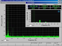
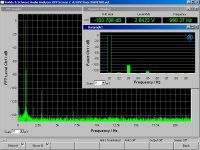
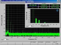
A while ago, we promised to test deliberate mismatch between N & P devices in the F5X.
We keep our promise, as always.
Here the measurement results.
The N FETs has Vgs of about 2.7V, the P FET 2.2V. So there is a huge mismatch.
NN & PP are matched to within 10mV, basically to the measurement repeatability.
Firstly one should look at the single ended F5.
This can be tested by grounding the X and measure only one (L or R) half of the balanced amplifier.
As you can see, there is a significant increase in second harmonics due to the mismatch Fig on the right), as expected.
We are currently testing a method to restore that balance (to lower 2nd harmonics). To be published later.
Patrick
Attachments


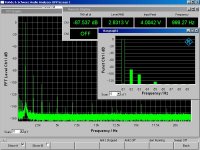
As we have always maintained, if the left and the right halves of the amplifier is identical,
the X configuration will cancel any residual even harmonics in balanced mode.
This you can see this even harmonics clearly in the figures below, showing THD measured in balanced mode.
Again the one on the right has the said mismatch.
Note that this is only the case if you are using a balanced input signal.
So while perfect NNPP match is still the ideal, a slight mismatch between NN & PP does not lead to disaster.
That is, if you are building the fully differential F5X.
")
More to come.
Patrick
the X configuration will cancel any residual even harmonics in balanced mode.
This you can see this even harmonics clearly in the figures below, showing THD measured in balanced mode.
Again the one on the right has the said mismatch.
Note that this is only the case if you are using a balanced input signal.
So while perfect NNPP match is still the ideal, a slight mismatch between NN & PP does not lead to disaster.
That is, if you are building the fully differential F5X.
More to come.
Patrick
Attachments
He who makes the accusation should provide the proof ??
Do you trust simulated results, or was there measurement backup ?
The F5X is not the F5, different devices, bias points, ......
So if you wish to verify the F5, you should ask those who have one, e.g. Nelson.
We'll eventually do a test on the F5X, out of curiosity.
But that would be after all the other stuff that we have to do that has higher priority.
Regards,
Patrick
So if you wish to verify the F5, you should ask those who have one, e.g. Nelson.
The F5 was designed for low distortion at 1 watt, which is about .0015%.
As the distortion vs bandwidth figures are quite good, I would not expect to
see any IMD test that showed high distortion at reasonable levels.
On the other hand, I only care about the sound.
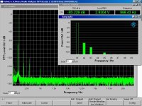
Further to the discussion in post #783, we have done more work on the compensation method and are ready to publish.
Attached from left to right are the single ended ouputs from an F5X :
on the left with properly matched devices,
in the middle with mismatched N-P devices (0.5V difference in Vgs),
and last but not least the same mismatched devices but with gain compensation by changing resistor values.
As you can see the compensation works, but not as perfect as I wanted it to.
So it still make sense to have properly matched devices, especially in singl ended mode.
The performance in balanced mode has already been discussed in post #784.
Thanks to dave for all the experimental work.
Patrick
Attachments
Does not seem to be a significant advantage to perfectly macthed devices over mismatched ones with gain correction. In fact, while the corrected graphs fets are slightly higher in distortion, their harmonic distribution looks better to me. what is your opinion on this EUVL. Is the lower overall distortion worth the higher harmonics. I know this applies only to SE input.
Firstly I do not see higher distortion for 3rd and 5th with any of the measurements, within the measurement repeatability.
You always have to look at numbers below -120dB with care.
What you see here is also closed loop distortion.
Maybe you should read what John Curl or Charles Hansen says about open loop linearity.
e.g. http://www.diyaudio.com/forums/solid-state/28853-sound-vmosfet-print.html?pp=50
Of course we'll then end up in the endless discussion about ho wmuch feedback is good or bad.
As I said in post#1, 100 ways to skin a cat.
I only intend to show you how I want to do it.
If you believe in numbers, then use opamp, or even Class D.
But then you ar ein the wrong forum.
Patrick
Thanks to dave for all the experimental work.
My pleasure Patrick.
In fact, while the corrected graphs fets are slightly higher in distortion, their harmonic distribution looks better to me. what is your opinion on this EUVL. Is the lower overall distortion worth the higher harmonics. I know this applies only to SE input.
The first graph deserves a little more explanation - That measurement was taken many moons ago when there was a noise issue on the bench from a florescent light. The low level, non-harmonic peaks are an artifact of the noise. And as Patrick points out, well below -120dB down. I was just a bit too preoccupied to convert it back to grounded x to re-measure now that the noise issue is solved.
Dave
They all look great. I was mainly pointing out that the nonmatched devices were very close in performance to the matched. Encouragement for those who do not get in on that particular pool of fets. Of course all this distortion is at vanishing levels and way below other amps i have listened to that sound great. I kinda like a little dirt in my music.
so what exactly is your "compensation method" and how is it applied/calculated for a given Vgs offset?Further to the discussion in post #783, we have done more work on the compensation method and are ready to publish.
I know I can shift the Vgs by changing by changing the value orf the source resistor, but I seem to remember that you told me that was "cheating"
It is a bit more complicated than that.
You do change the source resistor value, but in doing so you also change the drain resistor value of the 1st stage.
If you combine both effects, you can recalculate the open loop gain of the top & bottom halves to rebalance them.
And we have an excel sheet designed precisely for that.
But since all Batch 1 &2 subscribers (will) have perfectly matched sets,
and the balanced mode will also sort it out for independent builders with only NNNN PPPP match,
there is right now no real incentive for publication.
We shall publish when it becomes interesting, e.g. when all the NNNNPPPP sets have been used up.
Call me evil if you wish ......
Patrick
Thanks to Jan Didden's generosity, he has put my second article for Linear Audio online for free download :
http://www.linearaudio.net/images/stories/Didden LA V3 PK lr.pdf
This is based on the thermal design of the F5X power amplifier case.
Since the article was written, we have done more analytical work, and wish to publish two further supplements.
Patrick
.
http://www.linearaudio.net/images/stories/Didden LA V3 PK lr.pdf
This is based on the thermal design of the F5X power amplifier case.
Since the article was written, we have done more analytical work, and wish to publish two further supplements.
Patrick
.
Attachments
Hi Patrick,
interesting article. I´ve gone through this a few times building class-A power amps. One thing I don't understand is the big difference between the °K/W given for Kapton insulators from Fisher (0,07) and the value you calculate (0,44). See the data sheet below.
For my last few amps I´ve used the Kapton insulators and was quite satisfied. I think I even measured some temperatures not that far off the specs.
William
http://www.hifituning24.de/downloads/kapton.pdf
- Status
- This old topic is closed. If you want to reopen this topic, contact a moderator using the "Report Post" button.
- Home
- Amplifiers
- Pass Labs
- F5X -- the EUVL Approach