....
Anyone would like to help out with distribution of the resistors (and collect money, addresses, .... quite a bit of work involved) ?
....
I would be willing to distribute the matched sets among the European participants of the group buy.
However, I feel uncomfortable collecting money from them.
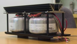
Another update -- Cradle with Transformer with the regulator heatsink.
This is only mock up for taking an early picture, as the sink has to be cut into 2 pieces with a 20mm gap in between, so that air can flow over a smaller length of the sink (factor of 8 less flow resistance).
All discussion between team, me and forum are finished and I am supposed to announce details. But we have a big customer meeting at work these 3 days, so I won't have time till Friday earliest. So my apologies for that. The case GB is not as simple as the resistor GB and needs some explaining.
Patrick
Attachments
Case GB info at :
http://www.diyaudio.com/forums/grou...se-user-distribution-check-2.html#post2539059
Patrick
http://www.diyaudio.com/forums/grou...se-user-distribution-check-2.html#post2539059
Patrick
An update on the PCB front, further to posts #72 & 87.
For those who are taking Option 2 of the case, and/or are 1:1 according to the prototype, these are the following PCBs you would need for 2 channels of F5X Dual Mono (separate transformers, one case) :
2x Main F5X PCB with daughter board and safety relay board, 70um double sided, available from DIY Audio forum, unlimited availability.
2x PSU PCB set, each including one regulator PCB and 4 capacitor PCBs, 70um single sided, probably available as GB with fitzfish, as these are of no general use without the case and hence probably limited in demand (max 50).
1x Control & Protection board, front panel mounted, 35um doubled sided, available from MarkLai as GB, as these are of no general use without the case and hence probably limited in demand (max 25).
There is an additional PCB already done by ashaw which has the same circuit as my control & protection board, but are laid out for general use. If there is sufficient demand, we shall make the Gerber files available to the forum so that they can make that available to you all (schematics will be published in due course).
The main amplifier PCB (and the PSU PCB) has been checked by me. Fitzfish is making the final corrections. The Gerber files will then be sent to Variac, and 10 prototype will be make to check for layout errors. Of the 10, 4 will go to AR2, 4 to fitzfish, and 2 to smyslow. They will have to burden to test the PCB for layout errors first, then go through the different circuit configurations, test, measure and report.
When the main Amp PCB has been tested OK and the forum ready to put them up at the shop, we shall publish the schematics, component placement diagrams, and the bill of material.
I shall gauge interest for the other PCBs later when the case subscribers have all confirmed their orders.
Patrick
.
Last edited:
Main Amplifier PCB is 80x120mm
MOSFETs are on a 120x80mm mounting pitch (hole centres).
Control & Protection board is 130x100mm.
Regulator Board is 29x134mm.
Capacitor Boards are 66x41mm.
(Caps are standard 10mm pitch snap-in, max. 30mm diameter x 50mm height, 8 in total)
Patrick
.
MOSFETs are on a 120x80mm mounting pitch (hole centres).
Control & Protection board is 130x100mm.
Regulator Board is 29x134mm.
Capacitor Boards are 66x41mm.
(Caps are standard 10mm pitch snap-in, max. 30mm diameter x 50mm height, 8 in total)
Patrick
.
Last edited:

Dave,
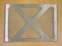
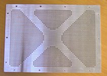
To enable trouble-free assembly for all, CNC drilled is standard :
http://www.diyaudio.com/forums/grou...se-user-distribution-check-2.html#post2539079
The mesh is not easy to mount tight onto the frame without distorting.
They were sourced by Mark from a local hardware shop.
But you can get good ones from McMaster-Carr.
Not cheap though.
Patrick
CNC = win
The CNC looks amazing! That's my vote.
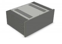
Alternative case for FX5 amplifiers
Patrick and I have been discussing a case I designed for my own personal use building the FX5 amplifier. It is a bit simpler than his and Mark's design and will be less expensive. There seems to be a tremendous amount of interest in building these amplifiers and I will consider making cases for others if there is enough interest to make production worthwhile.
Right now I am working on making first articles of the case and still have plenty of work to do. Once everything is checked out and the case is finalized, I will post more specifics and price a kit that is made specifically for the FX5 to gage interest.

Dave
Patrick and I have been discussing a case I designed for my own personal use building the FX5 amplifier. It is a bit simpler than his and Mark's design and will be less expensive. There seems to be a tremendous amount of interest in building these amplifiers and I will consider making cases for others if there is enough interest to make production worthwhile.
Right now I am working on making first articles of the case and still have plenty of work to do. Once everything is checked out and the case is finalized, I will post more specifics and price a kit that is made specifically for the FX5 to gage interest.
Dave
Attachments
- Status
- This old topic is closed. If you want to reopen this topic, contact a moderator using the "Report Post" button.
- Home
- Amplifiers
- Pass Labs
- F5X -- the EUVL Approach