Impressive results Dave! And also impressive lab equipment.
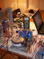
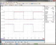
Attached a picture from my "kitchen table" and an additional scope plot. For this I've used my UGS-based preamp as a single to differential converter to get a balanced input voltage. The cheap USB-scope with build-in waveform generator doesn't give such a voltage. Now the results are much better than the former one, even without the cascode devices.
Uwe
Attached a picture from my "kitchen table"
and an additional scope plot. For this I've used my UGS-based preamp as a single to differential converter to get a balanced input voltage. The cheap USB-scope with build-in waveform generator doesn't give such a voltage. Now the results are much better than the former one, even without the cascode devices.Uwe
Attachments
Those who might like a very simple phase splitter to convert single ended signal to balanced might want to have a look at this :
http://www.diyaudio.com/forums/solid-state/200325-fet-based-phase-splitter-2.html#post2814583
Don't use this to supply the F5 for THD measurements.
Patrick
http://www.diyaudio.com/forums/solid-state/200325-fet-based-phase-splitter-2.html#post2814583
Don't use this to supply the F5 for THD measurements.
Patrick
So I am in the middle of testing the protection board. All seems to be going well so far. Current measurements:
The power supply ripple is 20mV on the +/- 12V rails and 8mV on the 5V rail.
Every part of the circuit that I have tested so far works.
Supply voltages are OK accurate (set by 7800 regs).
The power supply ripple is 20mV on the +/- 12V rails and 8mV on the 5V rail.
Every part of the circuit that I have tested so far works.
Supply voltages are OK accurate (set by 7800 regs).
Not quite yet, will finish testing tomorrow. However I cannot see anything going wrong there.
A general question: what would people prefer for connectors on this board?
No connector, just 0.8mm holes;
4 pin JST connectors;
The MOLEX 2mm connectors that are on the current board.
None of these will hold up the release of these boards.
A general question: what would people prefer for connectors on this board?
No connector, just 0.8mm holes;
4 pin JST connectors;
The MOLEX 2mm connectors that are on the current board.
None of these will hold up the release of these boards.
Not quite yet, will finish testing tomorrow. However I cannot see anything going wrong there.
A general question: what would people prefer for connectors on this board?
No connector, just 0.8mm holes;
4 pin JST connectors;
The MOLEX 2mm connectors that are on the current board.
None of these will hold up the release of these boards.
Molex 2mm connectors work for me.
Not quite yet, will finish testing tomorrow. However I cannot see anything going wrong there.
A general question: what would people prefer for connectors on this board?
No connector, just 0.8mm holes;
4 pin JST connectors;
The MOLEX 2mm connectors that are on the current board.
None of these will hold up the release of these boards.
I'd prefer 0.8mm holes.
Some further update :
Since the amp and regulator PCBs are working, Dave is preparing to release the standard configuration schematics in the next days.
He also suggested using a more professional vendor for the Case GB Beta PCB sets, as I am sure you all want the very best.
So he is making enquiry with his own vendor in the US.
As such, the case will only be shipped with the free CRC boards from us.
Alexis has also finished testing the protection board which is fully functional.
We found a small layout bug which is now rectified, and new test boards are ordered.
As soon as they are available, Alexis will test them again, and then we can release those as well.
So luckily towards year end, my tasks are almost complete, and it is time that you guys take over ......
Patrick
I have been asked about where to get F5X PCBs.
The F5X Case GB subscribers will get Beta PCBs from fitzfish (or us if he is too busy). See post #611.
These Beta boards (incl regulator & protection) fits the case, & are probably not useful for others.
The F5X amplifier boards Gerber files will be released to the DIYA forum spring next year.
It is then up to them as to when they would like to have them in their online shop.
This was the agreement as per October 2010.
Patrick
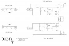
The schematics will be made public.
It's just a MOSFET follower with 2x RC filter from the rectifier.
Nothing special.
The PCBs are designed to fit the heat sink.
If you use similar sinks, you can also use the PCB.
There will be a new version of the protection board (PCB) for general use.
But that will take time.
Patrick
It's just a MOSFET follower with 2x RC filter from the rectifier.
Nothing special.
The PCBs are designed to fit the heat sink.
If you use similar sinks, you can also use the PCB.
There will be a new version of the protection board (PCB) for general use.
But that will take time.
Patrick
Last edited:
ahh i see, so just a little local FB to keep the voltage more stable? or is there some sort of reference? yeah i already have the same sinks, but not drilled, i bought some at the same time as sinks for my AJX.
i didnt think it would be something top secret, but thought perhaps you might be keeping it for your kit products. i'm glad you are releasing them though, so i can use the matched fets for a regulator as planned, rather than finding an amp project for them.
no worries on timing for everything, i have my hands full already, but nice to know there is stuff 'in the pipe' so to speak.
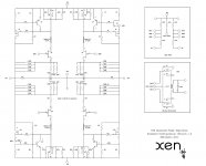
I know everyone has been waiting on technical details. The release schematics and the bills of materials for EUVL's F5X are here-
The build thread is in progress and will be posted as soon as the rest of the performance testing is complete, just a short few weeks away. We should also have some additional quotes for the PCBs back in the next week so that Patrick can make decisions about the PCBs for the case groupbuy participants.
Enjoy!
Dave
(file size limitations required splitting the amplifier BOM into three pieces)
"Edit : To avoid confusion BOMs are now only available here : F5X -- the EUVL Approach - The Build Thread"
http://www.diyaudio.com/forums/pass-labs/208880-f5x-euvl-approach-build-thread.html
Attachments
- Status
- This old topic is closed. If you want to reopen this topic, contact a moderator using the "Report Post" button.
- Home
- Amplifiers
- Pass Labs
- F5X -- the EUVL Approach