> what awg is that? 1|0?
I specified 4mm holes.
For the middle hole, I recommend using a M4 brass standoff plus brass screws and nuts to connect the main PCB, daughter PCB and Gnd wiring to the regulators and input XLR.
For the speaker outputs, you may use the same, or consider using 4mm copper tubes as output connectors.
As to soldering, according to my experience, there is no problem if you have a hot iron say 100W, even using lead free solder. Preheating the PCB in an oven to 80°C would also help, but not essential.
Patrick
aaah yes ok that makes more sense. i wonder if anyone makes copper standoffs? brass hmm i'm silly like that; i'd probably just use it like that till tweaked and replace with copper soldered. it wasn't so much the gauge that worried me, but the combination of gauge and being the centre of a pretty chunky ground plane and output ...ermm..trenches (trace just doesn't quite say it) that can suck the heat out of the iron as quick as you can give it. preheating the pcb would help.
looking good though; it takes 'low impedance ground node' to a whole other level
looking good though; it takes 'low impedance ground node' to a whole other level
Last edited:
nope, just copper for me if anything. although as you say it would probably be easier to find someone to make one from silver. I suppose i could use one of the online short run CNC fab sites popping up around the place.
also perhaps the amphenol buss headers would fit. then i could get SPC 70-140A capable connection radsok headers. i actually think they will fit. i'll dig up a link
something similar to this power block connector. but pretty sure there is one without the surrounding pins that you press fit.

though thats starting to get a bit carried away =)
also perhaps the amphenol buss headers would fit. then i could get SPC 70-140A capable connection radsok headers. i actually think they will fit. i'll dig up a link
something similar to this power block connector. but pretty sure there is one without the surrounding pins that you press fit.
though thats starting to get a bit carried away =)
Last edited:
> what awg is that? 1|0?
I specified 4mm holes.
For the speaker outputs, you may use the same, or consider using 4mm copper tubes as output connectors.
Patrick
Patrick
Have I misunderstood? Do you mean use Copernicus pipe as the actual connector that you attach your speaker cables to? If so, how do you attach the cables to make a good connection?
haha copernicus, indeed (stupid thing changed it to heat? wtf?) the predictive text here is actually getting on my nerves lately.
no what he means is copper tube to connect from board to chassis mounted connectors of your choice and i believe at least the GB have speakon and bayonet? speakon at least.
aayarrrrgghhhh so sick of having to go back and correct the stupid browser's 'corrections' its a forum engine thing isn't it? because its different with different forums and there is no way to change settings. we use so much jargon here that its incredibly frustrating
Last edited:
AndrewT,
Please kindly check your email at BT.
I have problems answering to your other address (bounces back with error messages).
For the other waiting, I hope to be able to confirm the PCBs functional within the next few weeks. If the main amp boards at the DIYA would take too long, those subscribed for the case only would have a chance to get Beta boards directly from me. Regulator boards and protection boards would be of no use to others because of the specific layout, so DIYA has not subscribed to providing them on the online shop. Which also means the case subscribers will get them from me also.
Hope Alexis would also be ready with the testing of the protection board soon.
Patrick
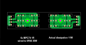
For those who might be interested, I did a CRC PCB for the F5X case as alternative to the regulator.
It has about the same voltage drop (2.7V) and hence dissipation, and uses 12x MPC74 1R per channel.
Board size is same as the regulator PCB (134x30). Same mounting, same wiring and connectors.
So direct replacement.
When there is sufficient interest, you can get the PCBs from us via a GB.
")
Patrick
PS You still need the regulator heatsinks for mounting, but also for the rectifier diodes.
.
It has about the same voltage drop (2.7V) and hence dissipation, and uses 12x MPC74 1R per channel.
Board size is same as the regulator PCB (134x30). Same mounting, same wiring and connectors.
So direct replacement.
When there is sufficient interest, you can get the PCBs from us via a GB.
Patrick
PS You still need the regulator heatsinks for mounting, but also for the rectifier diodes.
.
Attachments
Last edited:
Eventually yes, but we have a couple of minor issue to sort out first.
Do bear in mind the regulator is only one option.
There are people who swear by passive power supplies (e.g. THEL in Germany).
And NP is also using passive (CRC if I am not wrong) in his production F5's.
Especially in a balanced Class A amp, where the current draw is constant.
It is something worth trying out, IMHO.
Patrick
Don't forget Patrick that I will be testing a single transformer/dual CRC supply board version for comparison as well. If it works well, it will provide another, lower cost option for power supplies...
Similarly this testing will be a follow on to the full version with the regulators, so it will be a bit more time...
Dave
PS - bench supplies are here and repaired... more testing this weekend.
Similarly this testing will be a follow on to the full version with the regulators, so it will be a bit more time...
Dave
PS - bench supplies are here
and repaired... more testing this weekend.I used an F5 PS PCB in my Cascoded XF5 without issue. It uses Panasonic 0R47 resistors x4 for a total R of 0R12. I subbed an Antek 12V toroid to get to the 15-16V rails. Definitely not fancy, but it works for Nelson...it's good enough for me.
Total cost of the PS for my amp = $135 including Toroid, NTCs, resistors and PCB.
Total cost of the PS for my amp = $135 including Toroid, NTCs, resistors and PCB.
- Status
- This old topic is closed. If you want to reopen this topic, contact a moderator using the "Report Post" button.
- Home
- Amplifiers
- Pass Labs
- F5X -- the EUVL Approach