
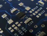
I soldered this by eye with a 1.6mm chisel tip hako-888 and a cheap hot air iron.
I would recommend you have three things: thin solder (0.45mm or less), liquid or tacky flux, and fine tweezers. You will need some IPA or board cleaning solution for afterwards though.
It does take a lot of time to solder this: took me about 5 hours.
I would recommend you have three things: thin solder (0.45mm or less), liquid or tacky flux, and fine tweezers. You will need some IPA or board cleaning solution for afterwards though.
It does take a lot of time to solder this: took me about 5 hours.
The first board always takes long. The second much faster if you do it right after.
I use 0.3mm solder for SMT, hot iron (420°C), magnifying glass and surgical tweezers.
Patrick
2

I see 240degC and 420degC.
These are not the same.
The 420degC is much higher than I dream of using.
That allows a very fast jointing time and that fast time may result in fewer failures of the semiconductors due to overheating.
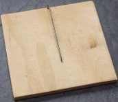
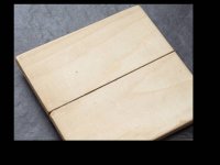
I copied this tool from a Member's post. Simple, cheap and effective.
Use a length of (15mm diam or 16g) spring steel bent into a long G.
The smd sits under the anvil and is held by gentle spring clamping action while the iron heats the solder pads/pins.
These are not the same.
The 420degC is much higher than I dream of using.
That allows a very fast jointing time and that fast time may result in fewer failures of the semiconductors due to overheating.
I copied this tool from a Member's post. Simple, cheap and effective.
Use a length of (15mm diam or 16g) spring steel bent into a long G.
The smd sits under the anvil and is held by gentle spring clamping action while the iron heats the solder pads/pins.
Attachments
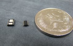
The Tssop ICs are easy to do with tack and drag soldering. The sot23 ICs can be done in the same way. The really hard parts are actually the electrolytic caps surprisingly. The only one that you may have difficulty with due to size is the SC-70 IC. But even that is not hard to do with an iron. It just might not be completely strait.
I do recommend that you get a hot air iron. They are cheap on eBay and they self align most ICs.
I do mean 240c. Actually some stuff was done at 220C.
I do recommend that you get a hot air iron. They are cheap on eBay and they self align most ICs.
I do mean 240c. Actually some stuff was done at 220C.
I copied this tool from a Member's post. Simple, cheap and effective.
Use a length of (15mm diam or 16g) spring steel bent into a long G.
In place of the spring steel, you can use a bicycle spoke (either a new one, or one cut from an old wheel). I've been using a jig like this for about five years. It really makes life easy, when positioning SMT components.
iron or gun in one hand.
solder in second hand.
tweezers in third hand.
second pair of tweezers in fourth hand.
or
Use the tweezers to position the smd on the solder pads while the first hand lifts the anvil.
Lower the anvil and pick up the solder.
Lay down the tweezers and pick up the iron/gun.
Start soldering.
solder in second hand.
tweezers in third hand.
second pair of tweezers in fourth hand.
or
Use the tweezers to position the smd on the solder pads while the first hand lifts the anvil.
Lower the anvil and pick up the solder.
Lay down the tweezers and pick up the iron/gun.
Start soldering.
This is what I do :
Pre-tin one pad of a device (e.g. a SOIC8) on the PCB.
Position device using tweezers.
While holding device with one hand, solder the device leg to the pre-tinned pad with the other hand.
Holding device with tweezers, solder a second leg (diagonally opposite).
Device now fixed in position. Can place down tweezers and solder the rest at ease.
QED.
Patrick
BTW, I know you are all eagerly waiting. Me too.
I have talked to the test team this week.
One is still on holiday (usual problem in Europe in the summer), and the other two are up to their necks with work.
I thought about releasing the Gerbers and the schematics. But I decided not to.
There is nothing worse if you all go ahead to do PCBs and buy parts, only to have to change later.
So please be patient with the team. We all have another life outside DIY Audio.
And it is a very good team that we have, I can assure you.
Patrick
ha, glad that got sorted, 420c hehe wow. i use the same method as Patrick and Ashaw, except as well as tinning one pad to start i use a touch of cardas organic no clean (but it needs cleaning to look nice) flux to enable it to flow very quickly. then drag solder and clean up with either a clean tip and a touch of flux, or braid with a bit of flux on it. with a bit of practice and modified landing patterns, you can even do parts that are not meant for hand soldering.
neat tool, maybe useful for some things, i'll give it a go, for most i think i'll stick to habit. a realyt nice set of pointy and curved tweezers makes it so much easier, its worth spending 30-50 on a pair imo.
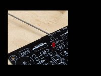
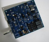
all except the LT1764A and LT3032 regs on this just used a standard 1.2mm chisel tip and this 4 layer board sinks to the ground plane so the tabs of the lt1764A needed a bigger tip. the DFN14 powerpad package regs were a bit tricky as they dont have leads, but still doable thanks to a custom land pattern and a couple of vias
neat tool, maybe useful for some things, i'll give it a go, for most i think i'll stick to habit. a realyt nice set of pointy and curved tweezers makes it so much easier, its worth spending 30-50 on a pair imo.
all except the LT1764A and LT3032 regs on this just used a standard 1.2mm chisel tip and this 4 layer board sinks to the ground plane so the tabs of the lt1764A needed a bigger tip. the DFN14 powerpad package regs were a bit tricky as they dont have leads, but still doable thanks to a custom land pattern and a couple of vias
Attachments
Last edited:
I too use flux, depending on the part I will use either a liquid RM flux or a tacky No clean flux. both do need to be cleaned afterwards though.
I also find that if you can still find it LMP solder is good, leaded eutectic solder with 2% silver. The multicore brand stuff is really good. (in australia you can still buy it).
That stuff flows sooo well with larger SMD stuff and through hole stuff.
Also never underestimate the power of good solder braid.
Also I would be careful about using an activated rosin flux if you are not going to clean the board. This stuff may be no clean.
On a further note, I am thinking of doing the IPC7711/7721 course in the next 6 months. That will be interesting.
Last edited:
Absolutely, the good stuff really is good (I use multicore stiff here too).
The good thing about the LMP stuff as apposed to the cardas stuff is you can get it really fine, down to 0.35mm. that is 0.014 inch. this is half the diameter of the cardas stuff. also the multiple flux cores is not a gimmick.
The good thing about the LMP stuff as apposed to the cardas stuff is you can get it really fine, down to 0.35mm. that is 0.014 inch. this is half the diameter of the cardas stuff. also the multiple flux cores is not a gimmick.
- Status
- This old topic is closed. If you want to reopen this topic, contact a moderator using the "Report Post" button.
- Home
- Amplifiers
- Pass Labs
- F5X -- the EUVL Approach