Hello passionate Pass personalities. ")
Quick and easy(?) question (and a few more buried in the text below…): Is it still worthwhile today to start building another Zen V4 amp, the 'Penultimate', in this day and age of F5s and other more recent developments?
Background:
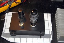
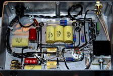
Having worked with electronics both as a hobby and professionally for a major part of my life, I have always had an interest also in HiFi. Yet except for building a fun little headphone amp (attachment 1 & 2, how many bugs can you find? ) about 12 years ago for my HD600s, I haven't really found time for major HiFi DIY projects up until now.
Recently a close friend and I decided this has to change. So we have teamed up and are trying to get our feets wet again, looking at things we might build, rummaging through our stashes and whatnot. It just so happens that he enjoys and has the facilities for metal- and woodworking, while I have been slinging solder for around three decades or so. So our skills complement each other pretty well.
Unfortunately neither of us have much in the way of experience when it comes to HiFi DIY, and we have to start somewhere. So for my part I am trying to come up with a few, small-ish amps and some inexpensive(?) spakers, so we have something to start working on. I have bought a pair of Audio Nirvana 10" FR drivers, which I expect we will have some fun with. But I need something to power those, of course.
Currently I am waiting for some parts for a peanut power SET amp, which will probably be the subject of a thread in the tube forum one day. However I would also like to build a small-ish yet good quality SS amp, just for comparison's sake. Preferably a well respected design, which won't cost a bundle. So I had a look in my Junkbox(™), and found I have most of the expensive parts for a low power (Id,q = 1.3A) Zen version 4, the Penultimate. Originally I was looking at the F5, but came up short on mains transformers. Thus my question: Do people feel it would be worthwhile in my situation to build a ZV4?
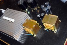
I found a pair of EI core 33Vrms mains transformers, (no load voltage, attachment 3), each weighing in at 3.5kg (7.7 pounds). The power resistor on the heatsink is 120mm long for scale. Reflected copper loss resistance on the single secondary is 0.36 ohm, resulting in a simulated load voltage of about 40-41V at 1.3A load current. This includes losses in a simple CRC filter, consisting of 2x 10'000 uF + 0.28 ohm, plus losses in an inexpensive Si diode bridge. I expect to drop the zener reference to limit the voltage loss across the cap multiplier in the ZV4.
Q: Are there any obvious problems associated with feeding the cap multiplier in the ZV4 with about 40V? This is a bit lower than the original.
Thermal design:
3x MOSFETs: 41V*1.3A = 53.3W.
Diode bridge: PF calculated to be rather exactly 3.0 in this case, with the first reservoir cap being 10'000uF. This gives a rough power loss in the diode bridge of 2*1V * 1.3A * 3 (PF) = 7.8W.
Mains transformer: VA load is roughly 33V * 1.3A * 3.0 (PF) = 129 VA. This should not cause problems for transformers of this size.
Loss for a transformer of this size is guesstimated to be about 7%. So power loss is (129/(1-0.07) - 129) = 9.7W.
Total heat load per channel is 71W, 142W for stereo.
The heatsink in the photo appear to be a Fischer SK102 profile, except this one is obviously raw Aluminium and not anodized black. It is 240mm long, 215mm wide and 83mm high (height of fins and 15mm thickness of the baseplate). If it is cut in two 120mm high sections, and each section was used as the side in a rack drawer, then each half would have a thermal resistance of 0.35-0.40 K/W (from Fischer catalog graph). This yields a temperature increase of about 28 degrees C, a bit too hot for comfort considering not all components within the chassis will be directly attached to the heatsinks. The lack of the black anodizing will further increase the thermal resistance above the published values.
So I am considering using the heatsink in a DIY cooling tunnel instead by combining the Alu profile with a pair of quiet, low speed fans. This should be more than plenty cooling even at very low air speed, and will also directly benefit the transformers by continuously replacing the air inside the cabinet.
What about heat distribution within each amp? If I go with passive cooling, then there shouldn't be a problem. I just attach the three MOSFETs and the diode bridge for each channel in a horizontal line across the heatsink on each side, a bit below the center line.
Hoever if I go for the cooling tunnel, then the amps will either run at different temperatures due to different distance to the fan end of the profile, the heatsink would need to be cut lengthwise (parallel to the fins) -and/or- the MOSFETS for each channel would not be operated at the same temperature. My thought is that the CCS might protect the amps from thermal runaway, and the per-device dissipation isn't that high anyway at about 20W.
----
Am I likely to run into hum problems with the magnetic fields from the EI core transformers, if I attempt to cram everything inside a single chassis?
Peak transformer currents are about 8A. I intend to use dual/dual, IE. separate PSU and main amp, star grounding, and true dual mono construction for the two channels, with anti-parallel diodes as ground loop breakers and inter-channel isolation.
----
Anything else I want to know about this amp? Over the last few days I have tried to read up on everything written about Pass amps, but am not quite there yet… Would be nice to know whether I want to keep an eye out for the missing parts, even though construction wouldn't start for quite some time yet.
In short: Comments? Criticism? Suggestions?
Thanks for having me (back).
- Frank.
PS: I am not known for my brevity, sorry.
Quick and easy(?) question (and a few more buried in the text below…): Is it still worthwhile today to start building another Zen V4 amp, the 'Penultimate', in this day and age of F5s and other more recent developments?
Background:
Having worked with electronics both as a hobby and professionally for a major part of my life, I have always had an interest also in HiFi. Yet except for building a fun little headphone amp (attachment 1 & 2, how many bugs can you find?
) about 12 years ago for my HD600s, I haven't really found time for major HiFi DIY projects up until now. Recently a close friend and I decided this has to change. So we have teamed up and are trying to get our feets wet again, looking at things we might build, rummaging through our stashes and whatnot. It just so happens that he enjoys and has the facilities for metal- and woodworking, while I have been slinging solder for around three decades or so. So our skills complement each other pretty well.
Unfortunately neither of us have much in the way of experience when it comes to HiFi DIY, and we have to start somewhere. So for my part I am trying to come up with a few, small-ish amps and some inexpensive(?) spakers, so we have something to start working on. I have bought a pair of Audio Nirvana 10" FR drivers, which I expect we will have some fun with. But I need something to power those, of course.
Currently I am waiting for some parts for a peanut power SET amp, which will probably be the subject of a thread in the tube forum one day. However I would also like to build a small-ish yet good quality SS amp, just for comparison's sake. Preferably a well respected design, which won't cost a bundle. So I had a look in my Junkbox(™), and found I have most of the expensive parts for a low power (Id,q = 1.3A) Zen version 4, the Penultimate. Originally I was looking at the F5, but came up short on mains transformers. Thus my question: Do people feel it would be worthwhile in my situation to build a ZV4?
I found a pair of EI core 33Vrms mains transformers, (no load voltage, attachment 3), each weighing in at 3.5kg (7.7 pounds). The power resistor on the heatsink is 120mm long for scale. Reflected copper loss resistance on the single secondary is 0.36 ohm, resulting in a simulated load voltage of about 40-41V at 1.3A load current. This includes losses in a simple CRC filter, consisting of 2x 10'000 uF + 0.28 ohm, plus losses in an inexpensive Si diode bridge. I expect to drop the zener reference to limit the voltage loss across the cap multiplier in the ZV4.
Q: Are there any obvious problems associated with feeding the cap multiplier in the ZV4 with about 40V? This is a bit lower than the original.
Thermal design:
3x MOSFETs: 41V*1.3A = 53.3W.
Diode bridge: PF calculated to be rather exactly 3.0 in this case, with the first reservoir cap being 10'000uF. This gives a rough power loss in the diode bridge of 2*1V * 1.3A * 3 (PF) = 7.8W.
Mains transformer: VA load is roughly 33V * 1.3A * 3.0 (PF) = 129 VA. This should not cause problems for transformers of this size.
Loss for a transformer of this size is guesstimated to be about 7%. So power loss is (129/(1-0.07) - 129) = 9.7W.
Total heat load per channel is 71W, 142W for stereo.
The heatsink in the photo appear to be a Fischer SK102 profile, except this one is obviously raw Aluminium and not anodized black. It is 240mm long, 215mm wide and 83mm high (height of fins and 15mm thickness of the baseplate). If it is cut in two 120mm high sections, and each section was used as the side in a rack drawer, then each half would have a thermal resistance of 0.35-0.40 K/W (from Fischer catalog graph). This yields a temperature increase of about 28 degrees C, a bit too hot for comfort considering not all components within the chassis will be directly attached to the heatsinks. The lack of the black anodizing will further increase the thermal resistance above the published values.
So I am considering using the heatsink in a DIY cooling tunnel instead by combining the Alu profile with a pair of quiet, low speed fans. This should be more than plenty cooling even at very low air speed, and will also directly benefit the transformers by continuously replacing the air inside the cabinet.
What about heat distribution within each amp? If I go with passive cooling, then there shouldn't be a problem. I just attach the three MOSFETs and the diode bridge for each channel in a horizontal line across the heatsink on each side, a bit below the center line.
Hoever if I go for the cooling tunnel, then the amps will either run at different temperatures due to different distance to the fan end of the profile, the heatsink would need to be cut lengthwise (parallel to the fins) -and/or- the MOSFETS for each channel would not be operated at the same temperature. My thought is that the CCS might protect the amps from thermal runaway, and the per-device dissipation isn't that high anyway at about 20W.
----
Am I likely to run into hum problems with the magnetic fields from the EI core transformers, if I attempt to cram everything inside a single chassis?
Peak transformer currents are about 8A. I intend to use dual/dual, IE. separate PSU and main amp, star grounding, and true dual mono construction for the two channels, with anti-parallel diodes as ground loop breakers and inter-channel isolation.
----
Anything else I want to know about this amp? Over the last few days I have tried to read up on everything written about Pass amps, but am not quite there yet…
Would be nice to know whether I want to keep an eye out for the missing parts, even though construction wouldn't start for quite some time yet.In short: Comments? Criticism? Suggestions?
Thanks for having me (back).
- Frank.
PS: I am not known for my brevity, sorry.
Attachments
Do you mean the cascode with a power JFET from Zv9? Was thinking about that one, but shaving still further down on my available voltage swing may not be the best of ideas? Also, if I understood NP correctly, then the bias chosen in Zv9, at least 2A, was critical to wring the performance from the power JFET. I was only planning on running 1.3-1.4A of bias.
Also, I don't know what they cost, but I have a suspicion I wont be able to buy those parts for what I pay for the IRFP044s. This was supposed to be a budget build...
Or maybe I just haven't gotten around to reading whichever article you are referring to?
Also, I don't know what they cost, but I have a suspicion I wont be able to buy those parts for what I pay for the IRFP044s. This was supposed to be a budget build...
Or maybe I just haven't gotten around to reading whichever article you are referring to?
No, however that is a move up in sound quality. I was reffering to the Semi South SJEP120R100 used in the First Watt J2. It would not be a cheap device. Probably at least 25USD ea. if not more. It has been discused in many threads here. It is currently used in an upgrade of the F2 for example. Try a search
I'm actually just waiting on any of the IRFP044 to break and I'll replace the gain mosfets with SS power jfets...maybe this summer. It's doing tweeter duties at the moment at 1.3A.
Also replace the mosfet buffers with 2sj74 jfets (Buffer for Blues) and you have an all jfet amp. I currently have the jfet buffers in place...do a search and you'll see the jfet upgrade suggestion from Mr. Pass.
Also replace the mosfet buffers with 2sj74 jfets (Buffer for Blues) and you have an all jfet amp. I currently have the jfet buffers in place...do a search and you'll see the jfet upgrade suggestion from Mr. Pass.
Last edited:
Thanks for the comments everybody. Have decided to slowly proceed with this project due to interesting developments. Please see below.
If you are referring to the headphone amp, then there is a little story behind the botique parts. Will save that explanation for another thread though.
But nice to hear about the JFET info, thanks!
Yes, I intend to do something like that, building everything modular for a start. Should allow for easier experimentation.
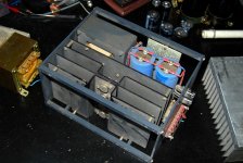
However I have to admit I sometimes wonder where I have my head. I just realized my stash contains a twin pair of industrial grade (if slightly dusty) 24V@10A linear, regulated power supplies. Looks like they date from around 1980, from back when they still made commercial, linear PSUs. They have floating DC grounds apart from chassis, so they can be configured as either +/-24V, or just plain +48V. Appear to be intended to be used with some form of external forced air cooling. The catch with using them would be running both channels from one set of power rails. Hmm?
Think the next step in this project would be to give those fellows a solid rebuild of some sort. Anyone taking bets on 30 year old 2N3055s and Sprague smoothing caps?
Status updates:
*) My calculation for the heat sinks in the first post is wrong. Had forgotten published thermal data is usually for a temperature rise of 80 degrees, and not 20. So need to multiply thermal resistance by 1.5 to compensate. However if I run the PSU external to the main amp, then the new thermal load calculation becomes 53W * 0.4K/W * 1.5 = 32 deg C. Still too high...
*) Ordered 3x low noise Papst fans.
*) Checked USPS website for status on my FR drivers. They are now out of customs, so any day now.
[...]
If you pay high end rates for RCA cables, $25 is very cheap,
and represents a really measurable jump.
If you are referring to the headphone amp, then there is a little story behind the botique parts. Will save that explanation for another thread though.
But nice to hear about the JFET info, thanks!
My good Sir! I intend to read everything here. No need to waste my time searching for particular subjects out of order.[...]
Try a search
Build the original design first, as you have the parts already, then enjoy the journey as you upgrade...you won't notice the subjective difference if you go straight to jfets.
Yes, I intend to do something like that, building everything modular for a start. Should allow for easier experimentation.
However I have to admit I sometimes wonder where I have my head.
I just realized my stash contains a twin pair of industrial grade (if slightly dusty) 24V@10A linear, regulated power supplies. Looks like they date from around 1980, from back when they still made commercial, linear PSUs. They have floating DC grounds apart from chassis, so they can be configured as either +/-24V, or just plain +48V. Appear to be intended to be used with some form of external forced air cooling. The catch with using them would be running both channels from one set of power rails. Hmm? Think the next step in this project would be to give those fellows a solid rebuild of some sort. Anyone taking bets on 30 year old 2N3055s and Sprague smoothing caps?
Status updates:
*) My calculation for the heat sinks in the first post is wrong. Had forgotten published thermal data is usually for a temperature rise of 80 degrees, and not 20. So need to multiply thermal resistance by 1.5 to compensate. However if I run the PSU external to the main amp, then the new thermal load calculation becomes 53W * 0.4K/W * 1.5 = 32 deg C. Still too high...
*) Ordered 3x low noise Papst fans.
*) Checked USPS website for status on my FR drivers. They are now out of customs, so any day now.
Attachments
- Status
- This old topic is closed. If you want to reopen this topic, contact a moderator using the "Report Post" button.
- Home
- Amplifiers
- Pass Labs
- ZV4 "Junkbox Delight" still worthwhile?