could you not add a serial R or RC to the speaker or OP to give the amp a more hospitable load to drive...???
Just a thought, EL
Well, No, would be my easy answer. That would change Qts, I guess, and muck up the bass responce.
But, let's explain it this way. I have 16 8 ohm speakers in 8strings of series pairs. 2 ohms. Because, it is said that even more than 1 speaker in series will cause one to suffer ill effects from the back emf of the others. I personally could not explain or understand that concept except to say that I find it less important of a problem if there are only 2 in series. I believe the paralell inductance of the group will also be lower making for an eaiser load on the amp. Additionally, less voltage gain is needed due to the lower output Z Speakers allowing less chance for the signal to be hosed up...

just an idea - there was similar or exactly same idea recently - why not combine F5 and F4 ?
something as mini F5 - same front end , but with nice 2SJ76/2SK213 "outputs" ..... say 100mA of Iq ...... driving multiple Toshiba final outputs in common source ;
so - count it as 2,5 stages ........
Speaking of different.
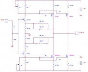
How about this one?
Edit: I was too lazy to add the gate resistors
I would go with your original idea first. As Nelson says two pair is enough.
I built up three a pair version a long time ago now, so it can be done, no problem.
Go for it
So, where was I... A few pics are in order.  I actually thought I would be raising more questions too? Once I decided to change the output configuration, I'm opening somewhat of a can of worms with the sound and the original design. It's difficult to judge How much things will change the sound or where I should be correcting for the changes. So far my changes are: 19V rails rather than the stock 24V, Dual output Toshiba FETs with .27 ohm Source Rs. in the output. And, the low Vgsth of the Toshiba's will require a smaller Drain R in the input stage to maintain the correct bias, I'll go with 620 ohms for now and stay with the 5k pot. With the lower Vds on the output transistors, I should be able to up the bias beyond the 1.3A stock value (2x of coarse) maybe as high as 1.6A/FET.
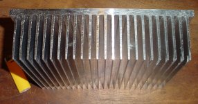
Lets see, 1st pic is a H.S. from HeatSink USA. 10.08" x 8" (200mm) section. This should be good for around .35C/W but we'll see. Bias is adjustable to optimize for available dissapation.
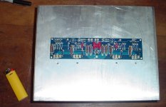
Second pic is the back of the H.S. with the mostly stuffed CViller board set up for dual outputs. FET holes are drilled and tapped, just gotta do some board mounting and H.S. mounting holes.
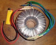
Last pic is 1 of the Antek 400VA 2X15 transformer(1/ch).
I actually thought I would be raising more questions too? Once I decided to change the output configuration, I'm opening somewhat of a can of worms with the sound and the original design. It's difficult to judge How much things will change the sound or where I should be correcting for the changes. So far my changes are: 19V rails rather than the stock 24V, Dual output Toshiba FETs with .27 ohm Source Rs. in the output. And, the low Vgsth of the Toshiba's will require a smaller Drain R in the input stage to maintain the correct bias, I'll go with 620 ohms for now and stay with the 5k pot. With the lower Vds on the output transistors, I should be able to up the bias beyond the 1.3A stock value (2x of coarse) maybe as high as 1.6A/FET.Lets see, 1st pic is a H.S. from HeatSink USA. 10.08" x 8" (200mm) section. This should be good for around .35C/W but we'll see. Bias is adjustable to optimize for available dissapation.
Second pic is the back of the H.S. with the mostly stuffed CViller board set up for dual outputs. FET holes are drilled and tapped, just gotta do some board mounting and H.S. mounting holes.
Last pic is 1 of the Antek 400VA 2X15 transformer(1/ch).
Attachments
Last edited:
Of course the problem is not driving, say 100 watts into
1 ohm, which implies 12 watts into 8 ohms. The problem
is that people with 1 ohm loads want a couple hundred
watts into 8 and over a kilowatt into 1. Even that's
do-able, but they want it to sound good also.
Since meeting demands like this requires a lot of hardware,
it's prudent to define what you actually want in advance.
50Watt @ 8 ohm with good sound will do ...
I recall that the ill fated Pass Monster project died out
just after I delivered a preliminary schematic.
Hmmm... the revival time might be upon us .........

I would go with your original idea first. As Nelson says two pair is enough.
I built up three a pair version a long time ago now, so it can be done, no problem.
Go for it
3 pr's with the standard front end or with cascoded front end ? ..
Well, because of the loss of gain by a factor of 4 in the output stage, when driving 2 ohms, 2 pair is necessary. Smaller Source Rs will help to a small degree. But, 3 pair would probably regain a similar gain figure to the stock F5. I'm willing to go the easy route for now. The CViller board is set-up for 2 pair of outputs.
As far as power, my goal was to drive 2 ohms relatively well. At 1.3A/FET, I should be getting over 25Wrms max output into 2 ohms. At 1.6A/FET, I'm doing over 40Wrms. On a speaker with over 100db efficiency that's more than I'll need.
As far as power, my goal was to drive 2 ohms relatively well. At 1.3A/FET, I should be getting over 25Wrms max output into 2 ohms. At 1.6A/FET, I'm doing over 40Wrms. On a speaker with over 100db efficiency that's more than I'll need.
3 pr's with the standard front end or with cascoded front end ? ..
Both standard and cascoded. However I used IRFP devices.
I tried both of my f5 amps with my stacked quads - they didn't play nice together.......
the highs had a touch of harshness that isn't in the amp with other "normal" speakers. But the main thing was that every now and then the source resistors would smoke on the f5. 9 times out of 10 it would be fine then on the 10th they would go.
I couldn't figure it out - not usual stuff like plugging cables when powered etc.
Fran
I tried both of my f5 amps with my stacked quads - they didn't play nice together.......
the highs had a touch of harshness that isn't in the amp with other "normal" speakers. But the main thing was that every now and then the source resistors would smoke on the f5. 9 times out of 10 it would be fine then on the 10th they would go.
I couldn't figure it out - not usual stuff like plugging cables when powered etc.
Fran
Instability ?
This works
from Unclejed613
"you might want to try a "quick and dirty" oscillation detector using an LED. you want to take an LED, put a 100 ohm resistor in series with it, then put a 4.7nf cap in series with the 100 ohm resistor. the "unused" leg of the LED becomes ground (polarity of the LED doesn't matter). the open leg of the cap becomes the input. then put a 1k resistor from the junction of the cap and series resistor to ground. the circuit is connected across the speaker terminals. any oscillation above 1 volt and above 20khz should light the LED, especially if the oscillation is continuous."
I built one and it works great for me. Attached is a pic. I check DC offset and for oscillation before ever attaching a pair of speakers to an amp..
The white resistors on the outside are the 4 ohm or 8 ohm dummy speaker loads. This way I don't have to attach the speaker terminals to the amp being tested...
Don't know if it would detect any and all oscillations...
I have the Sonus Faber Grand Piano Domus, bloody 4 ohm, and I still did not understand where I should stand. Maybe it's not such an extreme case.
I have the most standard ever F5 (no complains), would like to try the balanced (I tried one bridged channel).
But I am not sure if for me it's better to go with a parallel mosfet or the balanced. I have a balanced source, and I would like to use it as balanced. My case is not extreme, although I could not find on the network the impedance chart of my speakers, and I was always lazy to measure that (I have to kick out the family to put test tone in my speakers)
Any thoughts ?
D.
Many people design for peak power into 6 ohms. The amp obviously will do well into 8 ohms with dips etc. It will therefor not be a big strech to be driving 4 ohms. In the case of a stock F5, what will happen is the amp will leave ClassA operartion at maybe 1/2 the power into 4 ohms. It will continue to drive to the rail voltage in ClassAB mode. If the amp is designed with enough Bias to be optimized for a 4 or 3 ohm load, and stay in ClassA there will be excessive current and power dissapation for running it at 8 ohms.
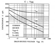
I intend to find some ussable compromise by using the parallel output capability, raising the bias and lowering the rail voltage. Raising the Bias should improve linearity of the output stage performance. However, lowering the rail voltage to much starts to put the output stage into the area of a MOSFETs capacitivly non linear area. Below 20V or so and capacitance rises very quickly in a very non linear almost logritmic rate, causing distortion and high frequency difficulties.
Idealy I would like to shoot for optimizing output power to a 1.5 ohm load. I want to drive a 2 ohm nominal load. I'm not sure I want to go quite that far as it limits effective use of the amp to very low Z loads. For instance, we can run rails of about 16V (as in Euvl's balanced design). We can then have 2A bias per output pair for a total of 4A while maintaining the output dissapation at 32W per FET. 128W static dissapation. This will give us at least 12Vout/1.5ohms=8A peak to the load, before leaving ClassA. Thats about 48Wrms into 1.5 ohms. Quite respectable numbers I would say or at very least, lots of headroom. Connecting this amp to a 4 ohm nominal load however, (3 ohm minimum) it will only drive 1/2 that power into the load, but still have the 128W static dissapation. That is about the equivalent of the stock F5 into 8 ohms but at double the static dissapation. Less efficiency, and, it does not have the rail voltage available to go any higher, classAB or not. Still quite respectable numbers and very suited to high effeciency speakers. If we connect this amp to an 8 ohm nominal/6 ohm minimum load, we then can only get 12V/6ohms=2A peak or 12Wrms ouput. That is an effecincy of about 10%!
So, although lowering the rails to +/-16V gets the job done quite well into a 2 ohm Nominal load, you would really want a different amp for higher imeadance loads. I'm thinking +/-19V rails with about 1.6A/FET bias is a good compromise. Ths should give a solid 9.6Vout into a 1.5 ohm load or 30Wrms while maintaining classA. It could conceivably drive 75Wrms ClassAB. A 3 ohm load could develope about 38Wrms in ClassA before running out of voltage. And, driving a 6 ohm load, about 19Wrms. These parameters would allow a peak output of about 45Wrms to be developed with a 2.5ohm load. Without a rediculous 10% effeicency performance but still giving reasonable output to the typical 4 or 8 ohm speaker.
In both the Balanced amp and the parallel output version, you still will be dissapating upwards of 250Watts total for both channels. Without lots of heat sink that's lots of heat. I beleive the balanced version is not as good at driving lower impeadance loads without some accompanying change in the sound due to the ClassA/ClassAB crossover point and other factors like gain and distortion. Euvl's design is optimized and tested for a 6 ohm load.
All this thinking is based on "first approximaton" numbers and calculations. No phase angle mismatches or resonace issues are considered here. I prefer to leave it up to the indavidual DIYer to his/her own compromise with their own requirements and expectations.
Last edited:

Thanks Patrick. So you think there would be little or no degradation using the 16V rails?
ZM, yep, 4:30AM for me. But, it's not just Sunday today is the Daytona 500. A big day for all of us non "1 ball" sportfans! More seriously, yep, I realize that but, optimizing for 2.5 ohms sounds like a very acceptable operating point for myself and most others.
ZM, yep, 4:30AM for me. But, it's not just Sunday today is the Daytona 500. A big day for all of us non "1 ball" sportfans! More seriously, yep, I realize that but, optimizing for 2.5 ohms sounds like a very acceptable operating point for myself and most others.
- Status
- This old topic is closed. If you want to reopen this topic, contact a moderator using the "Report Post" button.
- Home
- Amplifiers
- Pass Labs
- F5 For Low Z Loads ?