I added another 2.2k resistor in series on the channel that didn't bias fully, (Bring the total up to 6.6k!) and long story made short, it looks good!! ")
The amp is currently warming up as I type this, I am fully confident that it will be fine and thermally stable.
I have some good photos from this process, I should have those up later today or tomorrow morning.
The amp is currently warming up as I type this, I am fully confident that it will be fine and thermally stable.
I have some good photos from this process, I should have those up later today or tomorrow morning.
6L6, Jim.....
That's great news. From here, it's all downhill....!
Speaking about "downhill", I did some comparisons of the various Antec power transformers, based upon their own tech data. One would expect their 500VA and 600VA models to "outperform" their 400VA model, based upon output rigidity under loading, true? Guess what? Their own data doesn't back that up. (Huh?) I'll send you a spreadsheet tomorrow, with the suspicious data nicely plotted.
Again, enjoy your pending success tonight!
I won't bother you until tomorrow. I'd like a "second set of eyes" on the data I've collected. Makes me wonder about Antec, in general....
Ken
Hi Andrew
Can you recheck the 1.6A bias calc again, shouldn't it be 40.96W
Yep. Looks like a typo to me.....
Cheers Ken... that's what showed up on Google maps... so I presumed it was outdated. Good to know they are still around.
Ryan
Ryan
RKH...... OEM parts is back in their "original location" at 3029 North Hancock Avenue, Colorado Springs. Their phone is (719) 635-0771.
Ken
Well 6L6, it sure looks a pretty strange "something" you've got there .....
Perhaps you might take a few measurements of the voltage across that 6k6 resistor and check that the thermistor, pot, etc are actually the correct values - if your o/p fets are anything like standard, with about 4.2 volts across that 6k6 resistor in // with the pot and the thermistor+R, this should result in approx 1.3 Amps thru those o/p fets to give you that 0.6volt across the 0.47R o/p resistor.
If this is about right, then your o/p power devices are working okay and problem is elsewhere.
[....If it takes a 6k6 instead of a 2k2 to generate the 4.2 volts across this network, then something is definitely non-standard and as ZM mentioned, maybe the Idss of your jfets is quite low]
- do you know what it is?
If you have added the current limiting network, this could also be a problem source ....
It's good to relate some of the problems when building this amp, but it's just more guesswork without some measurements to follow your progress.
Antek Transformers
6L6, Jim (and Woody, etc)......
I dug a litte deeper into Antek's published specs for there 18-0-18 VAC torroid core transformer families. All data I used is from the Antek website. I've plotted the data in the attached. The info for the smaller transformers (100, 200, 300 VA) is mostly FYI. Please note that for each VA model I've plotted the three data points in the Antek specs, except for the 500 VA model, where the third data point (for the most heavy current load) was clearly erroneous.
Some interesting observations. The 500 VA model, based upon Antek's own data, is not a strong candidate for the F5, considering it's cave-in under loads; a little surprising for a claimed 500 VA model. Note that the Antek data suggests the 400 VA and 600 VA models are ALMOST IDENTICAL in VAC/current specs, to include voltage sag under load, up through the "expected" operational range for a straight-forward F5. (I'm certain some will chose to debate what "expected" operational range ought to be, but I'm considing that to be about 10 amps/rail, and close to the stated 18 VAC secondary. For those who want to debate, please feel free to start a new thread).
Also note the "blue dot", at about 18 VAC and ~3 Amps--that's where my curent 400VA transformer is working......pretty far below the Antek data for that model.
In any case, enjoy. All, FYI..... Again, all the "hard data" is from Antek itself. I'd be interested in others' thoughts........
Ken
I've been criticized for questioning the qualiy of the Antek transformers. All I can say is, I'm glad mine is Plitron.
Isn't each output device biased to 1.3A? Doesn't that mean that you are drawing more than 5.2A from the transformer?
In the F5 manual the amp as per Firstwatt a stereo F5 pulls about 180W from the wall, so for fun lets assume that the transformer has to provide about 160VA with a 1.3A bias per output device due to losses and such. That means you are drawing around 9A from the transformer at stock bias.
Measuring actual current in your circuit would tell you what you are really drawing in your amp, but I would say that it is far more than 3A.

Here are the photos of the initial powerup and the final tweaking/tuning.
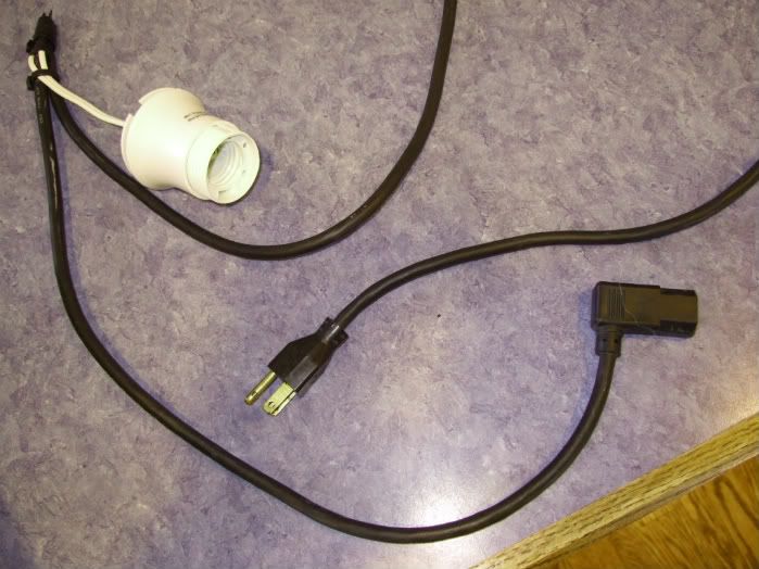
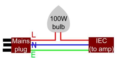
The powercord with series lightbulb. Although everything was ok, I'm glad that now I have this in my toolbox.
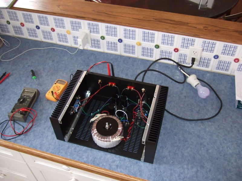
This is the photo taken before flipping the switch the first time... just in case something blows up...
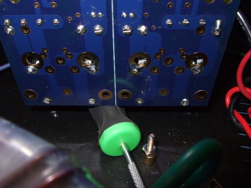
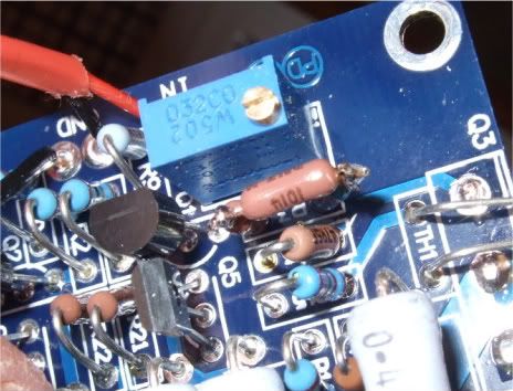
Previously I mentioned that one channel was not connected properly to the PSU, the wire on the pad just to the right of the screwdriver needed to be moved further to the right.
I am extremely happy that I chose to use spades connecting the wires to the rectifiers - without that, it would have been extremely difficult to get the board back up where it could be soldered.
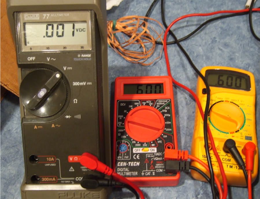
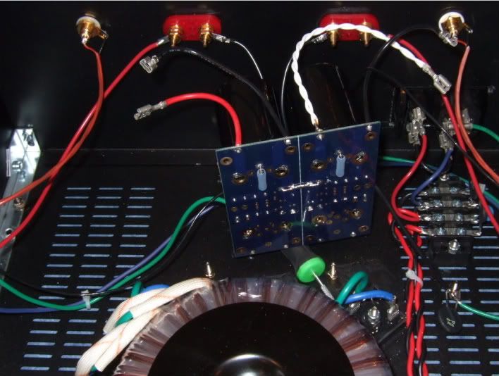
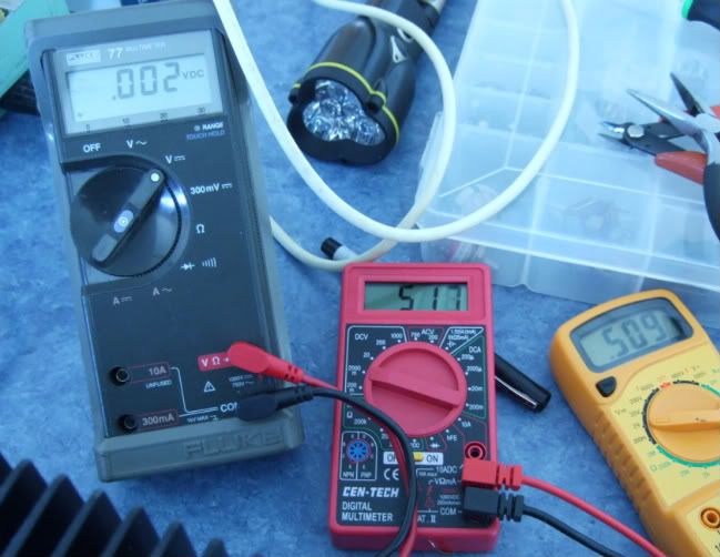
WhooHoo!!!!! YeeHah! This is going great! Sure, I am pretty much at the end of the potentiometer's adjustment, but look at those numbers! Let's go to the other side and make it look the same...
...
... And the results are nothing short of disaster. It's so bad that I don't even take a photo. The other channel is will not bias to more than .2v with zero offset, and the most bias I can get is only .45v or so, and that's with .4v offset! Ugh.
So the question is posed to the Gurus, and they say to increase the value of resistor paralleled with the pot. (R3, R4)
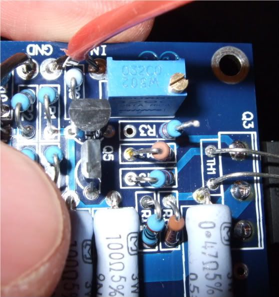
So out comes one lead.
In goes another resistor.
Twist
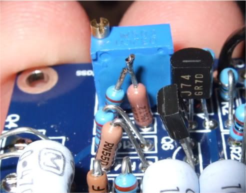
Solder and trim. Easy! (Well, desoldering something off a PCB is never fun, but no damage was done to the board. Whew!)
Ok! Let's look at the numbers!
Hmmm... That's it? .5v?? And this is at the end of the range of adjustment of the pot...
Well, the good news is that I did the resistor mod to both channels, and the 'good' one still biased up nicely, now with lots of adjustment left in the pot.
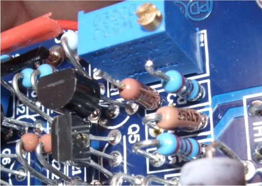
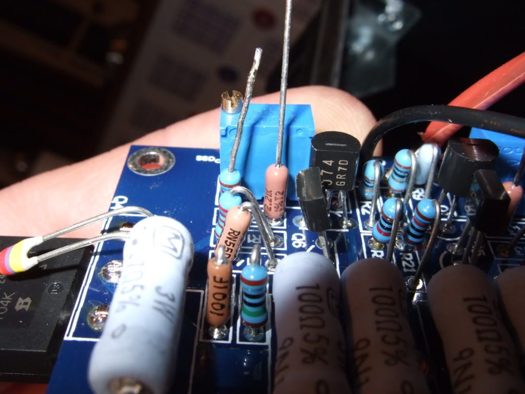
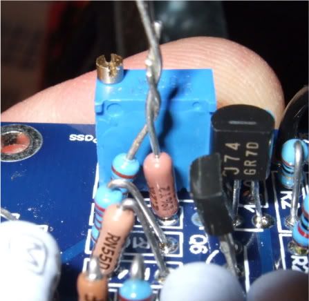
This time I really do not want to solder the board again, so I'm going to cheat and add another resistor to the ones already there. So the recently twisted leads are de-soldered and un-twisted...
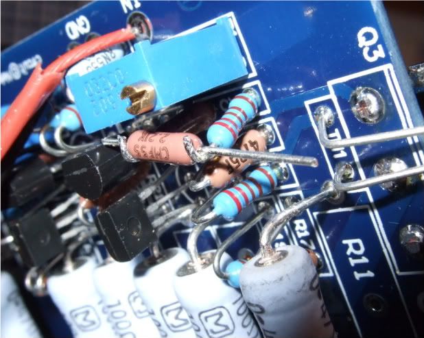
And another added...
And trimmed. Yes, it's not that pretty. Oh well.
...But it biases up beautifully! Hooray!!
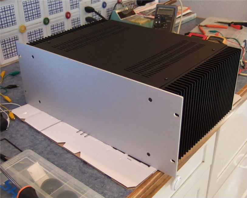
Here it is, all buttoned up and done.
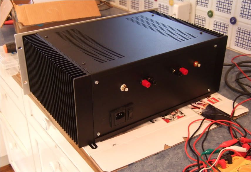
And the back.
And as NP said, "...And there you have it!!"
Oh, the Hiaku -
Building the F5
In solder fumes I smile
heat and balance sings
Or, if you are into 3-5-3
Pass amps are
in their special way
his and mine
The powercord with series lightbulb. Although everything was ok, I'm glad that now I have this in my toolbox.
This is the photo taken before flipping the switch the first time... just in case something blows up...
Previously I mentioned that one channel was not connected properly to the PSU, the wire on the pad just to the right of the screwdriver needed to be moved further to the right.
I am extremely happy that I chose to use spades connecting the wires to the rectifiers - without that, it would have been extremely difficult to get the board back up where it could be soldered.
WhooHoo!!!!! YeeHah! This is going great! Sure, I am pretty much at the end of the potentiometer's adjustment, but look at those numbers! Let's go to the other side and make it look the same...
...
... And the results are nothing short of disaster. It's so bad that I don't even take a photo. The other channel is will not bias to more than .2v with zero offset, and the most bias I can get is only .45v or so, and that's with .4v offset! Ugh.
So the question is posed to the Gurus, and they say to increase the value of resistor paralleled with the pot. (R3, R4)
So out comes one lead.
In goes another resistor.
Twist
Solder and trim. Easy! (Well, desoldering something off a PCB is never fun, but no damage was done to the board. Whew!)
Ok! Let's look at the numbers!
Hmmm... That's it? .5v?? And this is at the end of the range of adjustment of the pot...
Well, the good news is that I did the resistor mod to both channels, and the 'good' one still biased up nicely, now with lots of adjustment left in the pot.
This time I really do not want to solder the board again, so I'm going to cheat and add another resistor to the ones already there. So the recently twisted leads are de-soldered and un-twisted...
And another added...
And trimmed. Yes, it's not that pretty. Oh well.
...But it biases up beautifully! Hooray!!
Here it is, all buttoned up and done.
And the back.
And as NP said, "...And there you have it!!"
Oh, the Hiaku -
Building the F5
In solder fumes I smile
heat and balance sings
Or, if you are into 3-5-3
Pass amps are
in their special way
his and mine
Last edited:
Congrats! Everything ended just beautifull
It's been fun and and interesting following your thread. I have picked up a few things handy. Just in case I'll be using connectors on everything possible before I solder stuff up. Seems wise to have a few resistors at hand, even if you don't know when they could be used, so I need to get an assortment. Troubled with adjusting the bias, are one of the things putting me off this build, and others for that matter. Also the lightbulb thing looks like a nifty lil' gadget. I would appreciate if you could either post here or drop me a mail with the "how-to"
Again, congrats with a nice build
Pretty obvious maybe, but a practical thing is to mount an oldfashioned lampholder and some sockets on a piece of board, wood or otherwise.
Safest setup and at hands' reach for the next one.
Example pic : www.instructables.com/image/F041LU3FSSIKOIV/Old-World-Light-Bulb-Load.jpg
Safest setup and at hands' reach for the next one.
Example pic : www.instructables.com/image/F041LU3FSSIKOIV/Old-World-Light-Bulb-Load.jpg
- Home
- Amplifiers
- Pass Labs
- How to build the F5