Nice Build so far, any more pictures ?
Nothing very exciting at this moment. I am going through my boxes looking for and sorting hardware. Bolts mainly. #4-40 and #6-32. I am making a list for (hopefully) the last run to the electronics surplus store, I need a few very mundane things -- standoffs for the circuit boards, some heavier wire in different colors than I have here, some of those connector tab things for the IEC inlet and switch (and rectifier blocks).
I need to buy 2 thread taps, the aforementioned 4-40 and 6-32.
Question - do you need a insulating shoulder washer for the hole of a TO-247? Or can you just but a bolt straight through? Obviously you need a silpad or mica on the bottom of the case...
With the standoffs and the taps I can place everything and start drilling. Once the mechanical is complete then the rest will start shaping up very quickly.
CanAm man said:There are a lot of indirectly-lit pushbuttons available in the elevator cab (depends, of course, on how many floors the building has)!
I actually like that idea... But those buttons always seem to be orange...

The thread has taken a heck of a digression down the 'fancy power switch' path, which I am going to ignore for awhile... I will use the bat-handle I have on the back panel, and if I do happen across something that really trips my trigger, I will get it and put it in later. As it would be on the front panel, and it (the panel) is easily separated from the rest of the chassis, doing it later will be no problem.
Anyway, I have a couple of ideas for the front panel, I really like the blue back-lit "F5" like some members have done. Regardless, I am not going to worry about it for awhile.
6L6 , if you don't mind my inquiring about your hifi2000 case .
1 model #
2 cost
3 shipping time
i'm in the process of deciding on heat sinks and even though i have the skills to fabricate a case , when all is said and done , a ready made might be the better , more cost effective way to go .
cheers , Woody
1 model #
2 cost
3 shipping time
i'm in the process of deciding on heat sinks and even though i have the skills to fabricate a case , when all is said and done , a ready made might be the better , more cost effective way to go .
cheers , Woody
Mouser also carries those power switches
Mouser also carries those Bulgin switches:
MP0045/1E2BL012 Bulgin Pushbutton Switches
I used one in a gainclone/USB DAC I built a couple years back - I wired the contacts in parallel.
gaincard-usbdac - mpbarneyamps
Looking forward to seeing your F5 build!
Mike
Mouser also carries those Bulgin switches:
MP0045/1E2BL012 Bulgin Pushbutton Switches
I used one in a gainclone/USB DAC I built a couple years back - I wired the contacts in parallel.
gaincard-usbdac - mpbarneyamps
Looking forward to seeing your F5 build!
Mike
1 model #
"Pesante Dissipante 4U depth 300 mm" (6 1/2" tall x 11 3/4" deep x 19" wide) Which will have a different specific number depending on color and faceplate thickness. I needed to get the shallow(300mm) case, if you have the room for it, get the 400mm deep.
2 cost
$230.00 Exchange rate is at time of order. It was something like €104.00 with €60.00 for shipping.
3 shipping time
Ok, this is what sucks, basically a month. It was just a bit shy of that for me. The funny thing is that the delay wasn't Poste Italia, but the time it sat lingering in customs. I didn't know it was going to be that long, and it made the wait unbearable! If I had known, it wouldn't have been so bad.
when all is said and done , a ready made might be the better , more cost effective way to go
That was my idea as well... metal projects like this can get out of control very quickly if you don't have access to good tools, a good place to get scrap and cuttings, and a heatsink lined up. I thought about it for awhile, and realized that knowing the exact cost ahead of time is much better than a rat-race and indeterminate $$ trying to get all the necessary parts. Although $230 seems like a lot of money for a chassis, but it really isn't, when you consider the savings in BS.
Also, it is worth saying that the case is very, very nice.
Re edge-lit pushbuttons and "I actually like that idea... But those buttons always seem to be orange..." True story! It seems as though only the "higher end" hotels are using the blue ones these days. (LOL....)
Re: Taps--to save yourself a few trips, you might want to buy several in each size, and some tapping/cutting oil all in one trip--they typically are cheaper than the price of gas for the car (and multiple trips). There was a good, lengthy discussion on tapping Conrad (and other) heatsinks late last year in the forum.
You mentioned an electronics surplus store--I'm assuming in Denver. Can you share a name? I'm in Colorado Springs, and use "OEM Parts" down here--quite a collection of everything, if you have the time to weed through all the boxes and cubbyholes.
Anyway, I have a couple of ideas for the front panel, I really like the blue back-lit "F5" like some members have done. Regardless, I am not going to worry about it for awhile.[/QUOTE]
I think the vast array of choices and solutions is part of the fun of a project of this nature.
I chose the relay solution because it opened up switch choices, and it has the added benefit of keeping AC power away from the front panel. Less chance of noise/hum due to poor assembly from a poor assembler.
I hope to see more pictures of your progress soon.
I chose the relay solution because it opened up switch choices, and it has the added benefit of keeping AC power away from the front panel. Less chance of noise/hum due to poor assembly from a poor assembler.
I hope to see more pictures of your progress soon.
You mentioned an electronics surplus store--I'm assuming in Denver. Can you share a name?
Happily! J.B. Saunders -- although it's in Boulder...
JB Saunders Electronic Components, Test Equipment, Surplus
Here in Denver Fistells is still open, but they don't really have much that's worthwhile... (even though they have mountains of junk)
Well, no pictures at this moment but a little progress...
I traveled to Boulder (an easy 35min drive for me) to J.B Saunders and bought the remaining parts necessary.
Standoffs, wire, a bunch of those spade-things for the tabs on the rectifiers and IEC inlet that I don't know the name of. A couple of blue LEDs (obligatory, obviously...) and a ground lug for my Pearl Phono.
AC switch - remember how I mentioned that the Inlet Module I ordered had a lamp instead of a switch? The lamp is a snap-in component, and they happened to have a 15 amp switch that fits into the module! So that makes it exactly what I was after all along. That said, it doesn't have a great feel like the toggle...
Now I need to run to the hardware store in the morning, get a couple of taps and it's off to the races!!!!
I believe aircraft wire is the same as mil spec hookup wire. It's Teflon insulated tinned copper wire. For some reason it has less strands than the 105c PVC insulated appliance wire. Not that it will work any differently in the F5 but it looks cool. And the insulation won't burn back when you heat it. I got some on ebay and some from a couple of electronic surplus stores.
Throughly mundane update...
As mentioned earlier I needed to get a few more things before proceeding with the build.
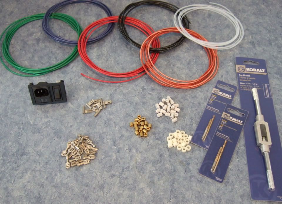
Specifically, wire, connectors, standoffs, spacers, and a tap set. (also a couple of ther things not photographed.)
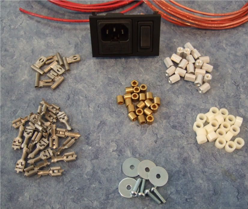
As I am not exactly sure what will be the best standoff/spacer, I bought an assortment. Brass, Nylon, and 'real' 6-32 thread standoffs. Also shown are the 1/4" connector spades, the 6-32 bolts and fender washers for mounting the power transistors.
Also note the Power Inlet module now has a switch!
Not photographed is a big pile of 4-40 hardware for mounting the boards, as well as a few more 6-32 bolts for the rectifier blocks and barrier strip.
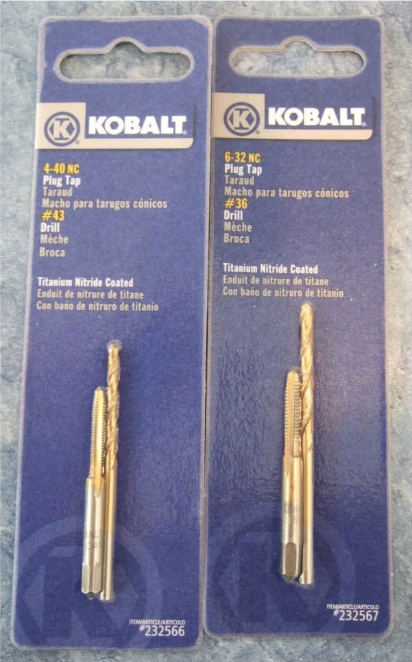
The store I went to didn't have taps without the drill bits, but since they are the exact size for the tap, I didn't see any disadvantage in getting them.
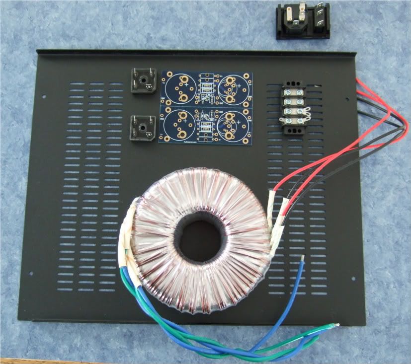
Trying to detemine the best layout for the bottom panel. The Transformer is positioned in the front of the case.
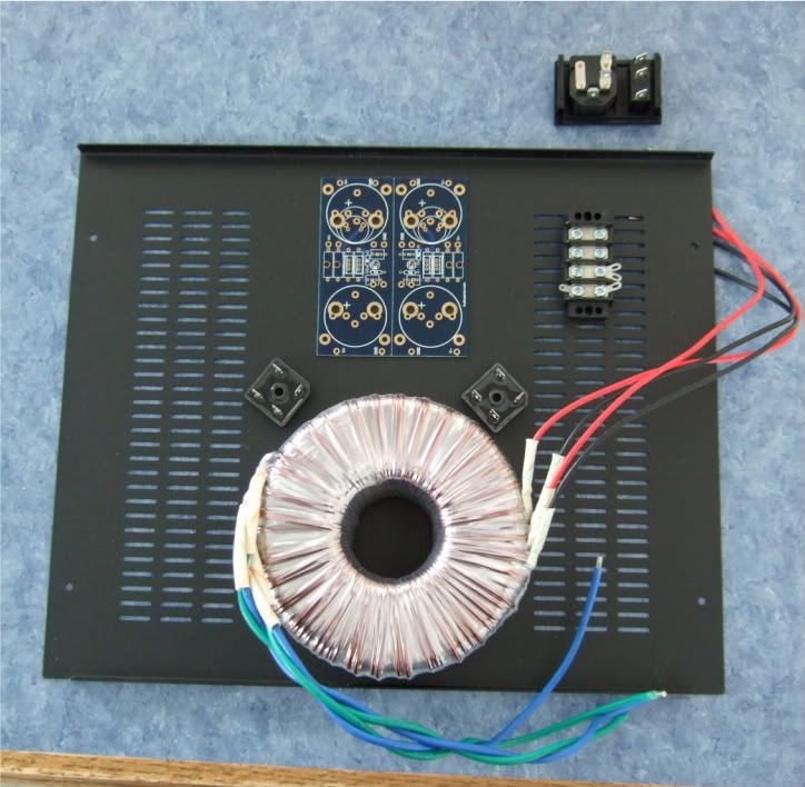
I like this better, it will lead to more symmetrical wiring. Which although not necessary, appeals to me.
If I had the 400mm deep chassis I would also have the power inlet and the barrier strip on the centerline.
I think it is a good idea to leave the chassis vents unobstructed, to keep the heat exchange/airflow as good as possible.
As mentioned earlier I needed to get a few more things before proceeding with the build.
Specifically, wire, connectors, standoffs, spacers, and a tap set. (also a couple of ther things not photographed.)
As I am not exactly sure what will be the best standoff/spacer, I bought an assortment. Brass, Nylon, and 'real' 6-32 thread standoffs. Also shown are the 1/4" connector spades, the 6-32 bolts and fender washers for mounting the power transistors.
Also note the Power Inlet module now has a switch!
Not photographed is a big pile of 4-40 hardware for mounting the boards, as well as a few more 6-32 bolts for the rectifier blocks and barrier strip.
The store I went to didn't have taps without the drill bits, but since they are the exact size for the tap, I didn't see any disadvantage in getting them.
Trying to detemine the best layout for the bottom panel. The Transformer is positioned in the front of the case.
I like this better, it will lead to more symmetrical wiring. Which although not necessary, appeals to me.
If I had the 400mm deep chassis I would also have the power inlet and the barrier strip on the centerline.
I think it is a good idea to leave the chassis vents unobstructed, to keep the heat exchange/airflow as good as possible.
Last edited:
I like option 2 as well...be mindful of a couple things - I learned the hard way...
1. placement of the feet
2. placement of the input jacks and speaker terminals...assuming they are going on the back panel.
3. orientation of the top and bottom...there is a "front" and "back"
I kept the AC power inlets towards the bottom more in the center area. I put the RCA jacks and speaker terminals high and more outboard.
There is a back and a front? That is very good to know!!! (And I am not being sarcastic, I honestly hadn't noticed yet.)
I was planning on mounting the feet to see about various fastener clearances, but I will also look at placements of everything with them installed.
My plan was to put the power module off center and low near the barrier strip. (As you suggest) The audio inputs and outputs will be arranged in a symmetrical pattern centered on the back plate.
(And I am not being sarcastic, I honestly hadn't noticed yet.)I was planning on mounting the feet to see about various fastener clearances, but I will also look at placements of everything with them installed.
My plan was to put the power module off center and low near the barrier strip. (As you suggest) The audio inputs and outputs will be arranged in a symmetrical pattern centered on the back plate.
Last edited:
one more gotcha...on the back you will notice that the lip of the top and bottom pieces "curl" over the back panel about 0.25" or so...make sure to give the power, RCA's and speaker terminals enough clearance...the end where the lip of the top/bottom goes all the way across is the back.
I was drilling the back of my Moskido VERY late one night...and maybe after a couple homebrews...ended up having to massively oversize the speaker terminal holes so that back lip of the top panel would sit properly...barely noticeable but I know its there...
I was drilling the back of my Moskido VERY late one night...and maybe after a couple homebrews...ended up having to massively oversize the speaker terminal holes so that back lip of the top panel would sit properly...barely noticeable but I know its there...
Last edited:
the size of the tapping drill determines the thread engagement.The store I went to didn't have taps without the drill bits, but since they are the exact size for the tap, I didn't see any disadvantage in getting them.
You can use a variety of different drill sizes for the one tap to produce different thread engagements.
Aluminium tends to use a smaller drill than for mild steel. Higher strength materials may use an even bigger drill size.
Use a high pressure lubricant for tapping (and drilling), although according to one Member I know nothing about tapping lubricants.
6L6, How would you feel if I were to also document my F5 build on your thread. I do not want to hijack or aything but, I'm at about the same stage as you are and another point of veiw I think would be good for at least the new Bs.
I have a dual output Toshiba MOSFET version in the works using CViller boards from the Forum (I guess thats second rev?). I'll be using HeatSink USA 10.08" heat Sinks and building a chasis/case mostly out of 3/4" oak. It will resemble a radio from the '40s when completed. I'm using 19V rails from a 400VA Xfrmr/ch, with a CRC filter.
I guess I could get off my butt and get some photo's?
- Home
- Amplifiers
- Pass Labs
- How to build the F5