The flow and returns to and from the rectifiers should also be twisted.
Bummer... The leads are too short now. Unless 2 or 3 twists will actually make a difference. ?
Last edited:
Bummer... The leads are too short now. Unless 2 or 3 twists will actually make a difference. ?
You need to strive for low loop area. Twisting is a better option, because it alternates the effect those wires have on adjacent circuits.
Can you get each Flow and Return pair much closer together?
did they need to be "very thick"?
what is the voltage drop along each of those wires?
What effect will that inherent resistance have on the peak currents flowing into and out of the rectifiers?
have you noticed I write rC in an rCRC supply.
That little r has a filtering effect. That little r is from the sum of the secondary winding and the wire going to the rectifier and the wire from the rectifier feeding the first smoothing cap.
Does it matter than the wires into and out of the rectifier have 1milli-ohm of resistance or 100micro-ohms of resistance? Would 5milli-ohms allow better performance?
did they need to be "very thick"?
+1.
Thinner wires that can easily handle the current demand can be routed much more efficiently. The tiny V drop may be of some benefit, as Andrew says.
Most houses wouldn't have walls thick enough to contain the wiring if the electrical code took cues from DIY audio.

The stoopid-thick wires on the transformer secondaries are that way from the factory.
The biggest question that I have is this - do you think it is advisable to cut the stock wires and splice in some smaller wires? I can't believe that the addition of a soldered splice is better than doing what can be done with the existing wires...
The biggest question that I have is this - do you think it is advisable to cut the stock wires and splice in some smaller wires? I can't believe that the addition of a soldered splice is better than doing what can be done with the existing wires...
Andrew T: Would it be useful to slip a braided shield over the transformer leads, as opposed to twisting them? I'm also running short leads on my build and twisting may not be feasible. (Having said that, I did shorten the transformer primary/secondary leads considerably to lessen the possibility of hum).
I can rewire (and twist) the leads between the rectifiers and PSU board, if you think this is wise. My build pics (showing my lead routing, etc) are posted in the Pass Forum, as well (under Another F5 build--beautiful music, different drummer).
I'd appreciate your thoughts.
Ken
I can rewire (and twist) the leads between the rectifiers and PSU board, if you think this is wise. My build pics (showing my lead routing, etc) are posted in the Pass Forum, as well (under Another F5 build--beautiful music, different drummer).
I'd appreciate your thoughts.
Ken
6l6.....
What if you moved your terminal strip (soft start parts) back closer to the transformer? Then you could rotate the torroid a little (clockwise) to give you additional secondary lead length to play with. Might give you enough leeway to twist the secondary leads, desipite their thickness. (P.S. I think I know what you mean--I'm using an Antek transformer, which appears to be the same as yours, and your secondary lead thickness).
What if you moved your terminal strip (soft start parts) back closer to the transformer? Then you could rotate the torroid a little (clockwise) to give you additional secondary lead length to play with. Might give you enough leeway to twist the secondary leads, desipite their thickness. (P.S. I think I know what you mean--I'm using an Antek transformer, which appears to be the same as yours, and your secondary lead thickness).
Bummer... The leads are too short now. Unless 2 or 3 twists will actually make a difference. ?
Just look at that picture and stop worrying about wires: http://6moons.com/audioreviews/firstwatt7/2_5.jpg
If you take cues from all diy audio suggestions, you will never finish your amp.
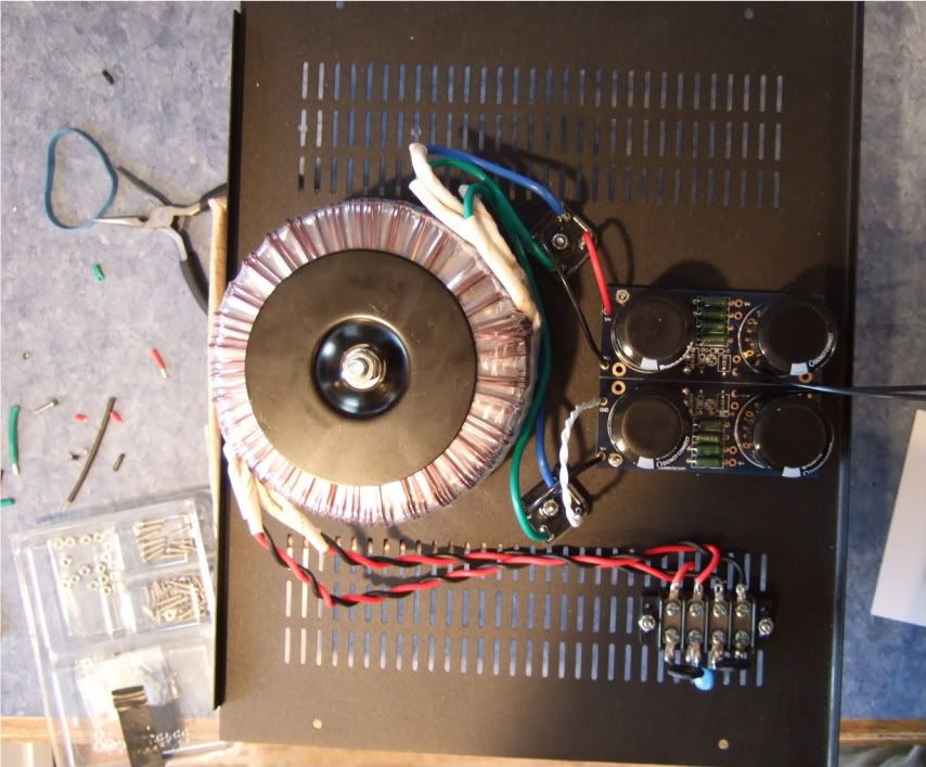
Wiring up the PSU...
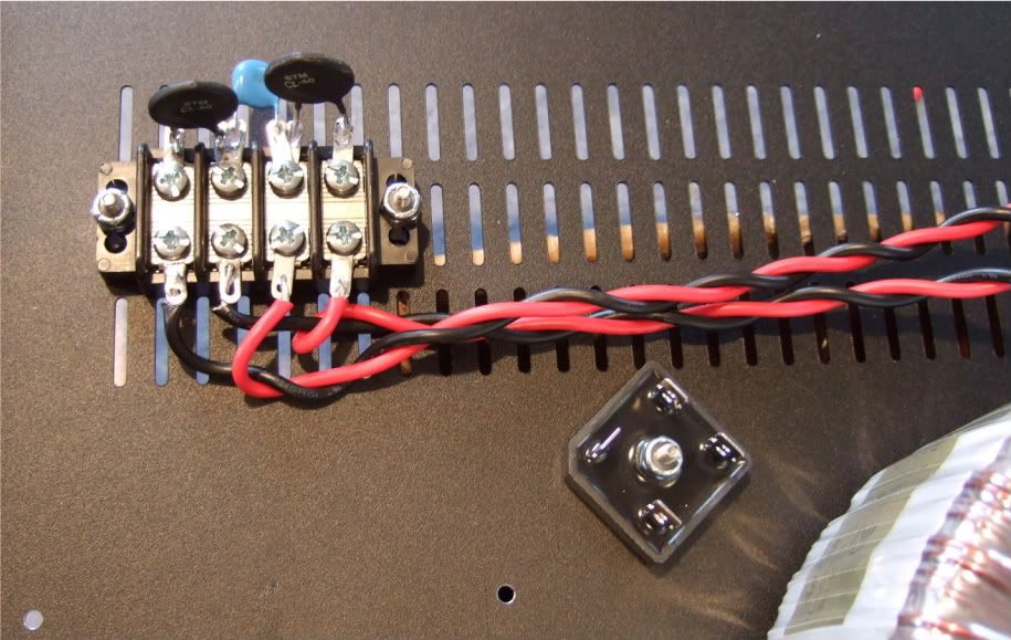
The primaries attached to the barrier strip. AC from the power inlet module will attach to the center two connections of the barrier.
Note the rectifier blocks -- the notched corner is "+" DC, it's opposite is DC "-" The other corners are AC in.
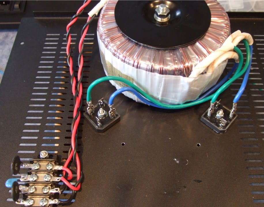
The leads of the secondaries connected to the rectifier blocks. Here you can see the AC connected to the AC in tabs of the rectifiers.
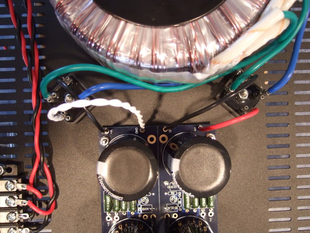
PSU board connected to the rectifiers.
The PSU completed except for AC in. This will be from the power inlet module. The black leads at the center of the PSU board will be the speaker negative connections.
Where are you going to mount the other TH1 (cl-60 termistor) to chassis ground?
If you take cues from all diy audio suggestions, you will never finish your amp.
Touche.
")
Where are you going to mount the other TH1 (cl-60 termistor) to chassis ground?
from supply caps CT/ground to mains earth/chassis
shown in F5 manual
mains earth is directly connected to chassis, if you have earth connection(earth rod/spear)
often directly from mains 'chassis' connector/plug
could be a yellow/green wire
so thermistor 'isolates' signal ground from earth/chassis
in preamps I have seen small resistor doing this job
I dont know if this is what's called 'ground lift'
Where are you going to mount the other TH1 (cl-60 termistor) to chassis ground?
I haven't decided yet, as I have yet to determine where the safety earth will go. Probably on the baseplate somewhere, on a dedicated screw.
Peter..... thanks. I, too, had the concern about the "twisted power leads", but after screening a lot of the pics in the F5 thread, I became less concerned. I set biases today or tomorrow. Almost there!
6L6: another lesson learned for me, regarding powder coating and grounding.... makes it TOUGH to get a good ground, after a chassis is powder coated (the coating even gets into drilled holes very effectively). I had to over-drill a mounting hole for one of the chassis feet--and tap it--to make certain I had a good effective "line ground".
6L6: another lesson learned for me, regarding powder coating and grounding.... makes it TOUGH to get a good ground, after a chassis is powder coated (the coating even gets into drilled holes very effectively). I had to over-drill a mounting hole for one of the chassis feet--and tap it--to make certain I had a good effective "line ground".
6L6
Wel I supose you could get a small block of copper and drill and tap there maybe even a bolt for the dirty grounds and a separate one for the cleaner grounds.
Then bolt that to the chassis.
Ops giving away to much.
One thing came to mind more than concern regarding twisting wires.
How hot are the thermistors going to be and how far that heath is going to go to the therminals.
Maybe you should have left them long and use ceramic beads
And no caps on the bridges?
I don't understand the question...
- Home
- Amplifiers
- Pass Labs
- How to build the F5