ok, something just went wrong .... ")
to test my newly built B1 i hooked it up to the power supply of one of my phono stages. I completely forgot that now I work with DC and connected + to - and the other way round. something started to smoke and smell before i could turn the power off. I have the impression that the input caps on the B1 ran a little hot but the smoke i believe came from a resistor on the power supply board.
i switched plus to plus and minus to minus, the power led on the B1 went on and it seems to work. I have the impression that the input caps on the B1 ran a little hot.
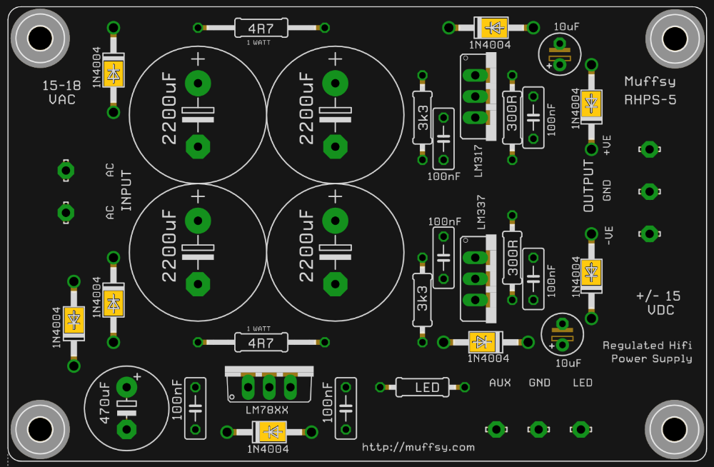
here's an image of the power supply. can anyone tell me which parts are likely to be damaged from the switched polarity?
also, are there any parts on the B1 i should check for damage?
to test my newly built B1 i hooked it up to the power supply of one of my phono stages. I completely forgot that now I work with DC and connected + to - and the other way round. something started to smoke and smell before i could turn the power off. I have the impression that the input caps on the B1 ran a little hot but the smoke i believe came from a resistor on the power supply board.
i switched plus to plus and minus to minus, the power led on the B1 went on and it seems to work. I have the impression that the input caps on the B1 ran a little hot.
here's an image of the power supply. can anyone tell me which parts are likely to be damaged from the switched polarity?
also, are there any parts on the B1 i should check for damage?
ok so i slept over this and now i realize that i'm really angry with myself for this stupid mistake. thanks Zen Mod for your help and I hope you have a little more patience with me.
I decided on the following. I want to get the B1 up and running first and troubleshoot the PSU later. I'll use the B1 with a different power supply anyways.
If I understand it right there's a possibility the transistors might have suffered some damage so I need to desolder them and match / test them, right?
Would this be a recommended setup for testing: Jfet matching setup
or this: 2SK170 matching
what other parts of the B1 could be damaged? I would think the Caps C1 and C2. Can i measure them or would it be better to replace them?
Best,
Michi
9V battery and you're good
Transistor matching
caps most probably survived , but you'll know everything if you go step by step
check JFets and be back with result
Transistor matching
caps most probably survived , but you'll know everything if you go step by step
check JFets and be back with result
all of this seems to be doomed for failure.
set up the test circuit last night with to discover that my multimeter doesn't measure current correctly. picked up a friends multimeter just now and measured the first jfet - circuit seems to work, now measuring the other ones.
set up the test circuit last night with to discover that my multimeter doesn't measure current correctly. picked up a friends multimeter just now and measured the first jfet - circuit seems to work, now measuring the other ones.
all of this seems to be doomed for failure.
......
you don't know my beginnings ..... was so enthusiastic , it's miracle I'm among the living

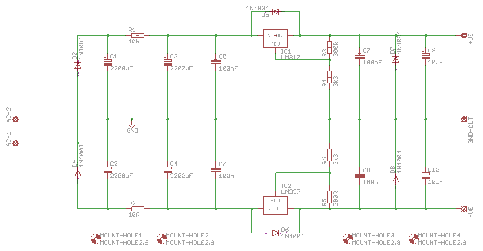
If you put a capacitor in parallel of r4/R6 you will improve the performance 10 times. See the datasheet of LM317.i think this should be the one:
i'll get some 1R resistors and measure according to your instructions.
Regarding the B1: what parts could possibly have been damaged? How do I find out?
I accidentally reversed the polarity when testing one of my synergy boards (they have 5 dc B1's on each plus some opamps). The only thing that was damaged were some 100uF caps on the opamps (they exploded).
So hopefully if your caps didn't explode you can see which resistor smoked and replace that and all will be fine
Tony.
So hopefully if your caps didn't explode you can see which resistor smoked and replace that and all will be fine
Tony.
If you put a capacitor in parallel of r4/R6 you will improve the performance 10 times. See the datasheet of LM317.
performance in terms of what?
I accidentally reversed the polarity when testing one of my synergy boards (they have 5 dc B1's on each plus some opamps). The only thing that was damaged were some 100uF caps on the opamps (they exploded).
So hopefully if your caps didn't explode you can see which resistor smoked and replace that and all will be fine
Tony.
luckily nothing exploded when i did it. might have to wear protection the next time i test a project.
first things first: thanks for all your help and advice!
so i measured all 4 jfets and they give me the following readings: 8,3mA, 8,28mA, 8,43mA, 8,42mA
looking at the spec sheet i assume those readings are right where they should be and closely spaced too. so does that mean that the JFETS are ok and i should solder them back to the PCB?
what to test next?
This is my first build and I have a few questions:
1) Most of the LEDs I've found specify 3.5VF and 5VR. Is R4 intended to step down the voltage for the LED? If not, what is it for and do I need to find a different LED for this project? Any suggestions?
2) The power supply I accidentally purchased is 24V (GST120A24-P1M Mean Well USA Inc. | Power Supplies - External/Internal (Off-Board) | DigiKey). I'm assuming this needs to be replaced with something like this: GSM60A18-P1J Mean Well USA Inc. | Power Supplies - External/Internal (Off-Board) | DigiKey. Is this correct?
3) On the board the holes for the input switch are labeled L1/R1, L2/R2 and blank. It seems obvious that L and R are channel left and right, respectively, and 1 and 2 are input 1 and 2, respectively. What are the unlabeled holes, the ground?
4) I'd like to add a power switch. I believe that the PS + goes from the center pin of the input barrel to the in of the power switch, and from the out (on) of the switch of the power + on the board. At the same time PS ground goes directly from the outer pin of the input barrel to the unlabeled power hole in the board. Is this correct?
5) And my last newbie question for today: why are the CW and CCW inputs for the volume switched between the left and right channels?
Many thanks for your assistance. Pictures shortly.
- Home
- Amplifiers
- Pass Labs
- B1 preamp build thread