As a pensioner I am naturally cautious with my money, but over the years have wasted almost as much on 'hi-fi' through ignorance as I have on fly
fishing!
It has always been my ambition to own a pair of horn speakers and I now have a partially completed set of Austin A166 (ESR versions), but need something to drive them.
There are now very few retail suppliers locally for components and my original intention was to build a Linsley Hood Class A, but I was seduced by the simplicity of the F5 and bought a kit advertised on eBay. I'd like to express my apologies to Mr Pass as I naively assumed that the boards were 'official', but have discovered my mistake on joining diyAUDIO.
My problem is the power supply for the monoblock F5s. I bought two toroidals, four bridges and a box of Nippon Chemi Comm KMH 35vdc/15,000uF capacitors and four 55uF motor run capacitors in
preparation, but also wasted money on the wrong inductors. Now after
browsing hundreds of pages I still feel that I am no closer to understanding the actual requirements of the F5 despite playing with PSUD for hours (JLH originally used a clever stabilized power supply).
It has been suggested that the largest capacitor should be second in the CRC network for the power supply and that CLC is better than CRC, but that the first capacitor should have a high ripple tolerance. Andrew(?) suggested that this could be achieved with multiple parallel low value capacitors (e.g. five 1,000uF would have better ripple capacity than a single high ripple 4,700uF capacitor). Inductors should be 2-10.0mH though mains frequency or load do not seem to be discussed in this context. I think that the KMH capacitors have a ripple level at around 3.72 amps and an ESR of 0.028 ohms.
Confused? Well I am. In the UK we have mains at 240 vAC and 50 Hz
frequency and I think that the F5 draws 1.3amps. I believe that bridge
rectifiers generate an erratic saw-tooth pattern that is then smoothed
through filtering. PSUD will not allow an inductor straight after the bridge, but I think that any capacitor in this position will be charged in bursts of energy that reflect the load and the mains frequency, which might cause problems for the transformer. In an old post it was suggested that a 4.7uF capacitor across the secondaries could prevent ringing in the transformer, but Steven(?) suggested that it was better
to place this across the +/- of the bridge rectifier.
Mr Pass simply uses CRC or is it CCRCC, but starts with bleed resistors. Please forgive my ignorance and failure to acknowledge contributors accurately, but what do members recommend as the best possible safe power supply for this amplifier given my purchases and the above.
Please do not cite the lovely Irish expression about reaching destinations,
which goes something like "... I wouldn't start from here!"

build up a mains bulb tester.
This will prevent damage to you or you equipment if you wire up any transformer wires wrongly.
It will also provide a lot of protection to the PSU and the zero biased amplifier when you are still new at the game. But, I keep repeating this. Use the bulb tester to power up EVERY new project and EVERY modified project.
Do the assembly in stages.
Start with the transformer alone. Wire it up as instructed and power it through the bulb.
Is all OK?
Add on the rectifier. is all OK.
add on each rectifier, checking each is OK.
ad on just four smoothing caps. One to each rectifier. Is all OK.
Start measuring input and output voltages as a final check that all is OK.
Understand what you have done so far.
You can either add on one channel of F5 or modify the PSU to your final arrangement. But again check in stages.
Slow progress is better than burnt components or eyes.
What building or test equipment do you have? DMM, scope, soldering iron, "helping hands", solder, magnifying glass?
Last edited:
My goodness, I have hardly sat down and you are kindly responding!
Zen Mod - I have twenty-four capacitors.
AndrewT - thank you for your kindness. I'll be careful, but still do not know quite what additional components I need for an excellent psu. Apologies, if I quoted you out of context.
Zen Mod - I have twenty-four capacitors.
AndrewT - thank you for your kindness. I'll be careful, but still do not know quite what additional components I need for an excellent psu. Apologies, if I quoted you out of context.
first and most important : you can always count that following Nelson's approach is safe bet
second : you can always do better ( in some things ) but there is possibility that overkill approach will not give any significant gain , in any area ( been there , done that)
third : it's easy to be confused , when you don't have enough knowledge ; taking step by step , as you obviously choose , is wise thing
now - what answer you prefer :
- fast and simple
-slower but thorough ?
for second one you need to provide more data for your xformers and caps
Zen,
the OP wants to know what to buy in addition to his existing stock.
He can build a simple PSU and that prepares him for the real job and also gives him knowledge on which to base his buying decisions.
I cannot tell him what is "best". He has to make informed decisions.
Start the build !
the OP wants to know what to buy in addition to his existing stock.
He can build a simple PSU and that prepares him for the real job and also gives him knowledge on which to base his buying decisions.
I cannot tell him what is "best". He has to make informed decisions.
Start the build !
Zen the problem is that I bought the capacitors before I really understood the requirements of the circuit. I am not technical, but felt that more is better without really understanding. I then discovered CLC and the issue of placing capacitors across the bridge. My original intention was to build a simple CRC circuit, but then a little knowledge is ...
Andrew I cannot really make an informed decision. My lack of knowledge is a limiting factor. Do I really need to spend a small fortune on buyng more capacitors, when I have quite a few that will suffice. PSUD seems to show that the first capacitor in the network does not need to be enormous, but must ripple tolerant. Hence my quote. 90,000uF per rail should be enough, but I do not know this for sure and I am concerned that I am missing something (e.g. the role of ESR).
Nick
Zen I'll have to dig out the transformers later today, when the boss is not around! It's a Saturday afternoon and I want to go on living. The transformers were 220v primary with dual 0-18v secondaries, but I'll have to measure the resistances and check the specifications. I assume that we are talking about pure resistance rather than impedance for the windings. The ESR for the capacitors is quoted in the opening post.
I have no idea what an EI choke is, but I am prepared to consider purchasing them (FOUR!). The amp is an on-going project and I am happy to spend more provided that it results in the superlative results that the F5 is reputed to produce though it might take a while. Thanks for your consideration and help. Nick
I have no idea what an EI choke is, but I am prepared to consider purchasing them (FOUR!). The amp is an on-going project and I am happy to spend more provided that it results in the superlative results that the F5 is reputed to produce though it might take a while. Thanks for your consideration and help. Nick
Hi,
don't buy any optional items until you become informed.
Start building with what you have and see how the PSU ends up and measures.
Then you can start taking informed decisions on the optional items.
A gapped EI choke is not cheap. 4 are expensive.
A 500gm bobbin full of enameled copper wire makes a fairly good air cored choke. You can buy suitable diameter wire on bobbins from swc if you decide to adopt rCLCC or rCRCLCC for the extra filtering that the L gives over the R
I would advise to build one channel without a chassis (just adequate heatsink) before you make any expensive purchases and just listen. Ask Questions along the way.
..... I assume that we are talking about pure resistance .......
exactly
........
I have no idea what an EI choke is, but I am prepared to consider purchasing them (FOUR!). ......
I'll give you a recipe for decent ~ 8mH chokes , good for at least 3Adc
when you measure what's asked for xformers , you'll see difference between CRC and CLC - I'll give PSUD files for both cases
considering amount of capacitance in which you invested , both approach will be overkill
CORRECTION - the transformers are actually Clairtronic Model 12081 300VA with dual 0-115v primaries and dual 0-18v secondaries rated at 8.33 amps. Regulation is quoted at 6.4% and they weigh 2.75 Kg each.
Transformer 1: Measuring the resistance of Primary A gives about 2.1 to 2.2 ohms with negligable secondary resistance (dropping from 0.3 or 0.4 ohms down to zero). The second primary and secondary values are identical.
Transformer 2: Primaries are both 2.1 ohms with about 0.1 ohms on the secondaries. My meter does not seem too happy with such low resistance!
Resistance between circuits is difficult to measure, but starts well above one mega ohm and the transformers are both labelled PASSED.
Thanks for your support. Nick
when you connect all 4 secondaries in series and measure the resistance you should get ~0r6.
Subtract the probe to probe resistance reading (say it's 0r1) and you are left with 0r5 for the four secondaries. Each secondary must be fairly close to 0r12
using the light bulb connect one transformer to your 240Vac mains.
The secondary should read 240 / 230 * 18 * 1.064 = 20.0Vac.
If your mains is different, the secondary open circuit voltage will be different.
Rather than spending more money I would start off with the same supply Nelson uses, ie CCRCC, or since you have 24 caps you could try quite a few different variations eg CCRCCRCC or CCRCCCC etc.
It is very easy to get addicted to this stuff and spend more time reading and learning than actually building.
Before you get addicted just build and keep it simple. As Zen Mod say's you can't go wrong following Nelsons design choices to the letter.
Once you have built and listened to it then go nuts trying everything under the sun.
Last edited:
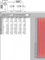
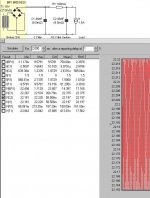
as I promised :
PSUD sims for for CLC and CRC
in both cases assumed two bridges per xformer , each cap cell made of 3x15mF
choose whichever you want and don't loose your sleep over it
edit :
will edit files and repost , I made one mistake
PSUD sims for for CLC and CRC
in both cases assumed two bridges per xformer , each cap cell made of 3x15mF
choose whichever you want and don't loose your sleep over it
edit :
will edit files and repost , I made one mistake
Attachments
Last edited:
- Status
- This old topic is closed. If you want to reopen this topic, contact a moderator using the "Report Post" button.
- Home
- Amplifiers
- Pass Labs
- F5 monoblock power supply for 50Hz mains