Here are some pics from my recently built Pearl 1.
I got this project from a friend who had too many projects, the Pearl was always something I was very interested in, I even kept the magazine with the original article init all these years. Of course, by the time I thought I wanted to build one, the PCBs from PassDIY were long gone.
The best way I could thank my friend for this was to complete it, and I must say that it's wonderful!!
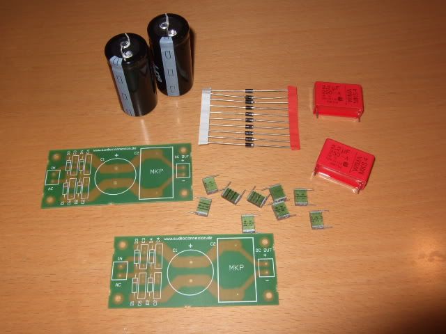
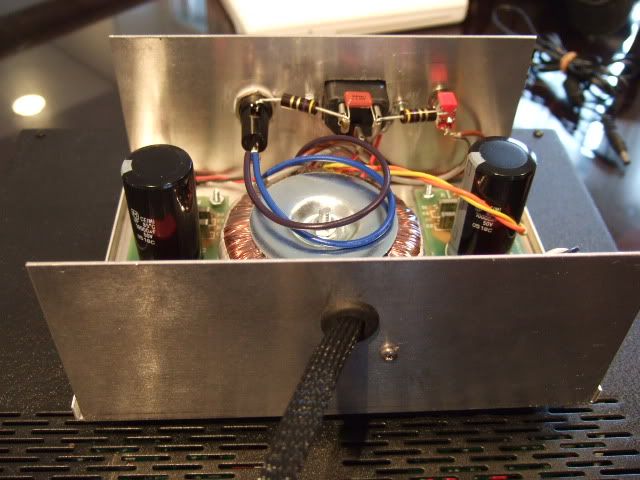
One of the things in the goodie bag from my friend were these nifty boards that were implemented as the rectifier and first bit of capatacance in the PSU. The snubbers are .1uf and the Wima is a 2.2uf. These values were selected mainly because they were the proper voltage and fit the board.
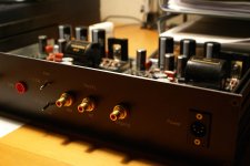
Complete!
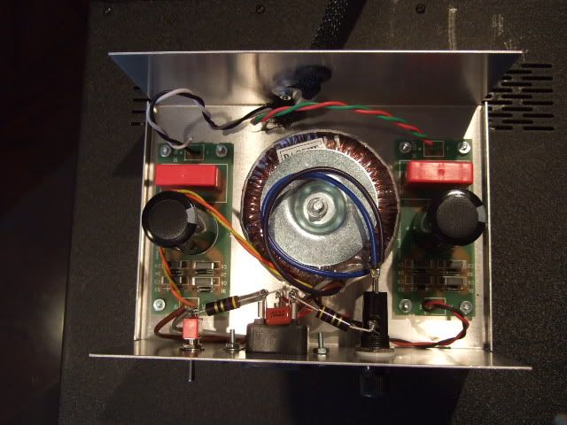
This is the temporary PSU enclosure. The wires and such are not trimmed because of it. I am looking for a nicer looking box. The PSU was built per the article, the Transformer is an Avel-Lindberg, it's quite nice with zero mechanical hum.
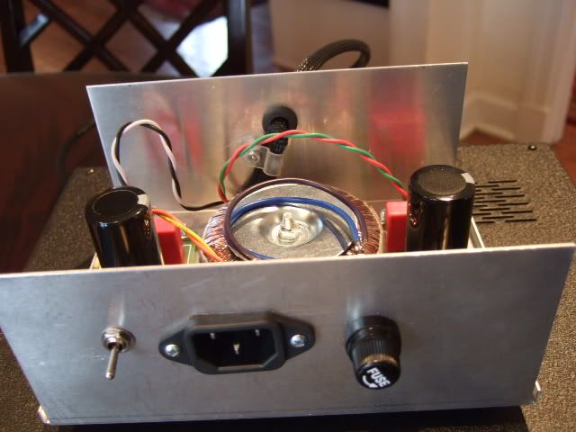
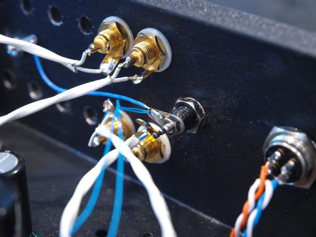
The power umbilical is just some 4-conductor wire with a flex sheath, cleverly jammed through a grommeted hole in the chassis. The strain relief is there for obvious reasons.
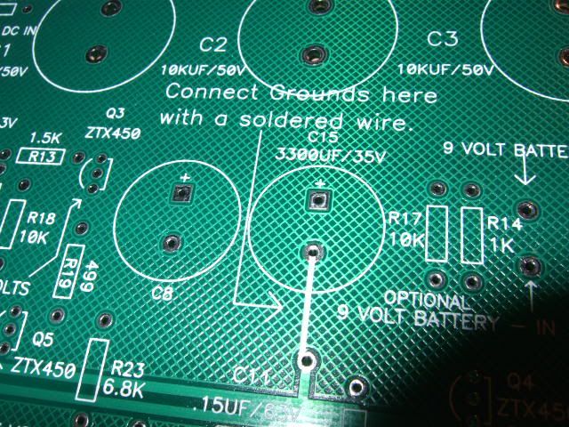
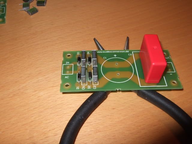
One quick note - these are the revision 1 boards, and in this position there should be a wire connecting the 2 pads where the white line is. I did it, but on the bottom of the board with the cathode lead of the capacitor mounted in that position. I thought I was being clever to do so... I would suggest a bare solid wire here, probably raised of the PCB by at least a MM or 2, as this is where the ground lug connects. More on this later...
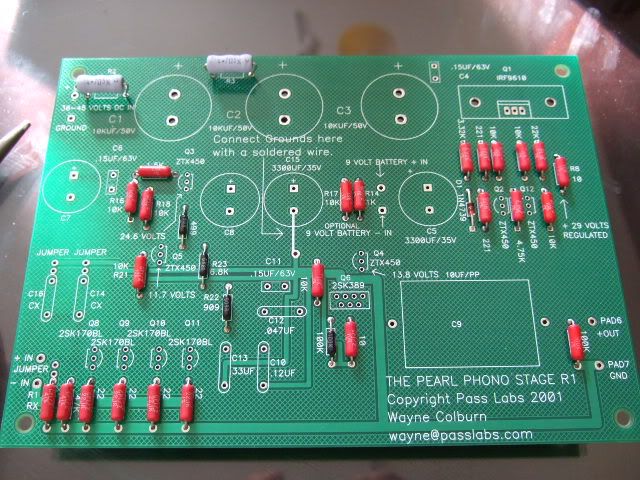
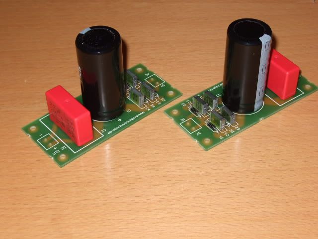
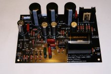
This is the only 'during' photo of the board stuffing that I have. I think the red PRP resistors look really pretty on the green board. The little black ones are from the RIAA-pack that PassDIY sold for a time.
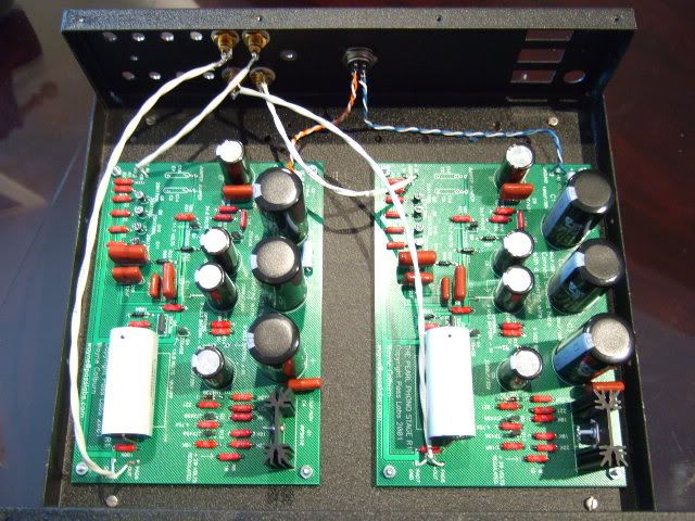
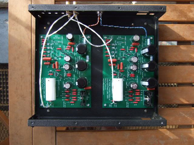
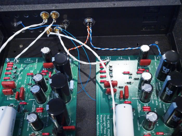
So this is how it's wired right now. The umbilical comes through the mic connector and attaches to the PCBs. The RCA in and outs are floating on the chassis and also attach to the PCB on their respective pads. This schema is quiet enough that I haven't needed to mess with the grounding for the last 2 weeks.
But, as a DIYer, you know that you can never leave well enough alone...
I have a Rega Planar 25 turntable and it's tonearm, the RB600, does not have a separate grounding lead. Hence the reason why I (currently) have no ground post.
Remember what I said about the bare wire that I so cleverly didn't put on the top of the PCB?? Well that is where you are supposed to connect the ground post. I would like to have one, if only to be able to take to other people's houses and show off just how good this circuit is... Anyway, the post is supposed to float on the chassis and connect to those spots. So, I need to get in there and do that.
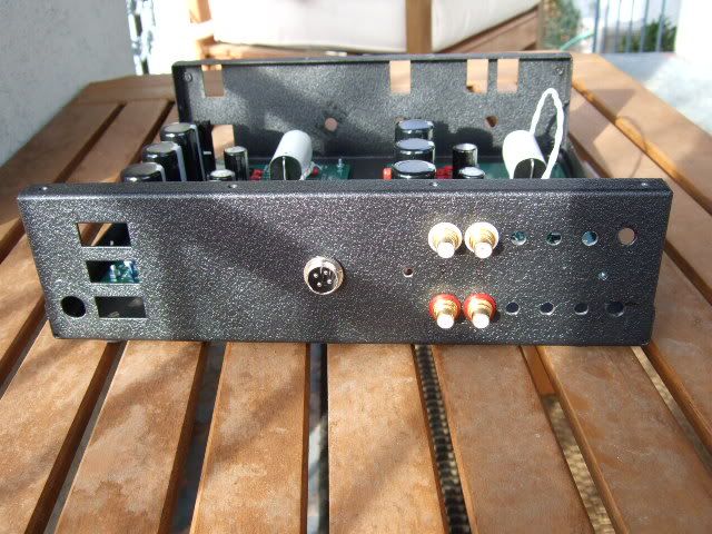
The back. I will go to a trophy shop and get some panels made to hide the holes and label the connections.
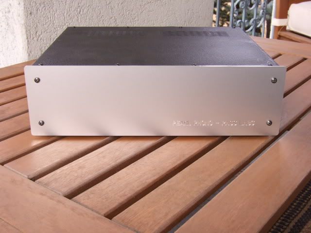
Front Panel Express is responsible for this project actually looking good!
The chassis is from an old Audio by VanAlstine preamp that I had years ago. The chassis was way too nice to throw away, and it sat for many years hoping to have a good project installed it it. That day is finally here.

I got this project from a friend who had too many projects, the Pearl was always something I was very interested in, I even kept the magazine with the original article init all these years. Of course, by the time I thought I wanted to build one, the PCBs from PassDIY were long gone.
The best way I could thank my friend for this was to complete it, and I must say that it's wonderful!!
One of the things in the goodie bag from my friend were these nifty boards that were implemented as the rectifier and first bit of capatacance in the PSU. The snubbers are .1uf and the Wima is a 2.2uf. These values were selected mainly because they were the proper voltage and fit the board.
Complete!
This is the temporary PSU enclosure. The wires and such are not trimmed because of it. I am looking for a nicer looking box. The PSU was built per the article, the Transformer is an Avel-Lindberg, it's quite nice with zero mechanical hum.
The power umbilical is just some 4-conductor wire with a flex sheath, cleverly jammed through a grommeted hole in the chassis. The strain relief is there for obvious reasons.
One quick note - these are the revision 1 boards, and in this position there should be a wire connecting the 2 pads where the white line is. I did it, but on the bottom of the board with the cathode lead of the capacitor mounted in that position. I thought I was being clever to do so... I would suggest a bare solid wire here, probably raised of the PCB by at least a MM or 2, as this is where the ground lug connects. More on this later...
This is the only 'during' photo of the board stuffing that I have. I think the red PRP resistors look really pretty on the green board. The little black ones are from the RIAA-pack that PassDIY sold for a time.
So this is how it's wired right now. The umbilical comes through the mic connector and attaches to the PCBs. The RCA in and outs are floating on the chassis and also attach to the PCB on their respective pads. This schema is quiet enough that I haven't needed to mess with the grounding for the last 2 weeks.
But, as a DIYer, you know that you can never leave well enough alone...
I have a Rega Planar 25 turntable and it's tonearm, the RB600, does not have a separate grounding lead. Hence the reason why I (currently) have no ground post.
Remember what I said about the bare wire that I so cleverly didn't put on the top of the PCB?? Well that is where you are supposed to connect the ground post. I would like to have one, if only to be able to take to other people's houses and show off just how good this circuit is... Anyway, the post is supposed to float on the chassis and connect to those spots. So, I need to get in there and do that.
The back. I will go to a trophy shop and get some panels made to hide the holes and label the connections.
Front Panel Express is responsible for this project actually looking good!
The chassis is from an old Audio by VanAlstine preamp that I had years ago. The chassis was way too nice to throw away, and it sat for many years hoping to have a good project installed it it. That day is finally here.
Last edited:
Remember what I said about the bare wire that I so cleverly didn't put on the top of the PCB?? Well that is where you are supposed to connect the ground post. I would like to have one, if only to be able to take to other people's houses and show off just how good this circuit is... Anyway, the post is supposed to float on the chassis and connect to those spots. So, I need to get in there and do that.
I think this is relatively important if you're hooking up to other peoples gear. I didn't do what you propose, and lost a 2SK389 when I connected my Pearl up to a friend's all tube preamp. I now keep a spare.
Very nice build, BTW. Thanks for sharing.
jeff
Getting the ground lug installed and properly connected will happen as soon as I can find a good post. I also need to play around with grounding the chassis, as it does pick up hum if you touch it. (It's steel, BTW)
Still, the circuit sounds better and better as it's getting settled in, much better than the QUAD I was using previously. (Which is still quite nice)
This project going as smoothly as it did has gotten me off the fence to build an F5.")
Still, the circuit sounds better and better as it's getting settled in, much better than the QUAD I was using previously. (Which is still quite nice)
This project going as smoothly as it did has gotten me off the fence to build an F5.
Getting the ground lug installed and properly connected will happen as soon as I can find a good post. I also need to play around with grounding the chassis, as it does pick up hum if you touch it. (It's steel, BTW)
Still, the circuit sounds better and better as it's getting settled in, much better than the QUAD I was using previously. (Which is still quite nice)
This project going as smoothly as it did has gotten me off the fence to build an F5.
You'll love the F-5. I dont know why everyone doesnt build one. Very nice project. Now I need to get my Pearl2 and Pumpkin Pre amp done!
Russellc
Nice build
I am Building one myself and having some questions.
Do you still have this wire under the pcb?
I was reading the post and I cut mine away
Now I am turning on the power and have some odd readings on my volt-meter.
I wasn't supposed to cut it away did I?
Off Corse I can restore them but I want to be sure now.
regards John
I am Building one myself and having some questions.
Do you still have this wire under the pcb?
I was reading the post and I cut mine away
One quick note - these are the revision 1 boards, and in this position there should be a wire connecting the 2 pads where the white line is. I did it, but on the bottom of the board with the cathode lead of the capacitor mounted in that position. I thought I was being clever to do so... I would suggest a bare solid wire here, probably raised of the PCB by at least a MM or 2, as this is where the ground lug connects.
Now I am turning on the power and have some odd readings on my volt-meter.
I wasn't supposed to cut it away did I?
Off Corse I can restore them but I want to be sure now.
regards John
Attachments
I finally connected the ground centers (the jumper on the board between C15 and C11) to a grounding post. It quieted it down a bit. Then I poked around with an alligator clip to see where the chassis needed to be connected to the circuit boards, and the grounding post was a good place. It really quieted down induced hum and now I can touch the chassis with only a very minimal increase in hum. It used to be noticeable when it was touched, and now it's only detectable if the volume is turned all the way up, far past normal listening levels.
Photos to be posted soon.
Photos to be posted soon.
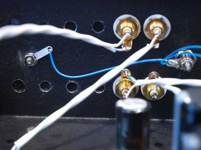
Ok, sorry about the long wait, here are the photos of the grounding -
The very thin blue wires are attached to the ground point, which is under the board. It actually was easier to have it on the bottom, not having to work your solder iron around the tall caps and components is nice. The bottom was wide open by comparison.
The ground post is isolated from the chassis. I wanted to try this first to see if it made a difference. Although the circuit was (somewhat) quieter with just the ground centers attached to the floating post, it was noticeably quieter with the chassis attached to the post.
The chassis is connected here, the tab has lock-washer crenelations and the chassis is bare of paint at the point of attachment. I chose this location only because there was an existing hole there. The chassis is steel, and difficult to drill.
I do not have the PSU IEC earth connected to the RIAA box. The safety earth is only in the chassis that holds the PSU. The umbilical has only DC + and - , those connect to the RIAA circuit board, and never touch the chassis.
What noise I have in the circuit is the same regardless if the PSU is powered on or not, and even if it's connected or not! There are no bleeders in the power supply, the circuit will run for about 40 seconds once the power is off. About 30 seconds if you unplug the umbilical completely. There is a lot of supply capacitance.
I need to try a groundbreaker on the RIAA chassis connection. That will be my next step.
can you share scheme v2?
I'm not sure what you mean...
I will be happy to help, can you be more specific? Thanks!


- Status
- This old topic is closed. If you want to reopen this topic, contact a moderator using the "Report Post" button.
- Home
- Amplifiers
- Pass Labs
- Pearl (one) Build