I like to built a HI HI -END , a univesal , true/pure class A opamp base on N.PASS circuit to replace my current opamp in my cd player . I need somebody to help me on this . My dac is SM5872 .
What type of mosfet/JFet should i choose ? Wide feq ,high current
high power low s/r .......s/n ...... ? and i know the voltage from DAC is very low ~ 0.3V i guess. How to mod this circuit to work and output around 2~2.5V ? OR resistor network that i can direct drive my power amp ? thank you ! *** If anyone know the PASS D1 DAC opamp circuit diagram please let me know !****thank a lot !
Attachments
I think you are a bit mistaken on your facts. The SM5872 is a voltage output DAC and the datasheet gives an output voltage of 2.0 Vrms typical. So you need more like unity gain from your circuit.
Also I think it would be wise to plan at least some sort of low pass filtering as the DAC is high oversampling one and your amp may not respond very well to that amount of high frequency content.
Ergo
Also I think it would be wise to plan at least some sort of low pass filtering as the DAC is high oversampling one and your amp may not respond very well to that amount of high frequency content.
Ergo
In CD67 the first dual opamp per channel is for low pass filtering and the HDAM is for output buffering. I've experimented quite a lot with this analog stage. I have replaced the opamps with LM6172 (similar to tweak on www.tnt-audio.com) and also tried to leave out the HDAM. I didn't like the sound without buffer though. It seemed to be too much for opamps to drive the load and almost all aspects of sound suffered....
Ergo
Ergo
Hi ergo, that meant in Marantz cd player opamp is not the main problem to enhance the sound . How u tweak your CD player ? My player everything ok but only the mid(vocal) i like to improve ! It not as smooth as CD63 mkII KI . I like to improve in this area . U got any ideal ? Thank .
CD67 mods
Well this goes out of the Pass Labs thread, but here goes
The first mod I would suggest is to remove the four electrolytics (in series with output arranged back to back) and replace it with a jumper wire. Just in case check the DC at output. It shouldn't be more than few mV and thus give no problems... These caps work with no DC bias on them and electrolytics are poor sounding connected like that.
The second very rewarding mod is to tweak the clock of CD67.
Check the thread
http://www.diyaudio.com/forums/showthread.php?threadid=985
for this subject.
Mr. Martin Clark (http://www.acoustica.org.uk) and I came to pretty much identical clock mod (part replacement on pcb) independently and also our finding of great sound improvement seem to be similar. He even has images of how to carry out the mods on his page. Mine is very similar I just don't have the extra voltage regulator for clock circuit.
Ergo
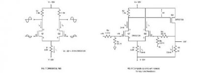
The D1 uses DACs whose output is a current
source and is designed to drive a virtual ground;
something that the SuperSymmetric circuit
intrinsically offers.
This type of DAC lends itself best to simply driving
a common Gate or cascode transistor without
feedback, and it works perfectly.
In your case, you have a high voltage output. Perhaps
you can simply put a passive low pass filter on it and
send it directly into your preamp.
- Status
- This old topic is closed. If you want to reopen this topic, contact a moderator using the "Report Post" button.
- Home
- Amplifiers
- Pass Labs
- diy opamp ?