At that point you're not far off from the regular X amp... Just use a differential pair, folded cascode with a VGS multiplier, and a follower output stage. Seems easier and probably better than using two cascaded common source stages- amounts to a single voltage amplification stage and a driver, with the differential pair shared for both halves (ready to add X feedback). I have simulated it, and it works well.
If you want to "X" ZV5, you would be looking to attach
the Source pins together in two identical ZV5's. Since
the circuit is phase inverting, the "cross" feedback is not
employed - it remains as with the ZV5 circuit - the communication
between the two halves occurs through the Source pins of
the gain devices.
Is this enough of a hint?
 /
/ 
the Source pins together in two identical ZV5's. Since
the circuit is phase inverting, the "cross" feedback is not
employed - it remains as with the ZV5 circuit - the communication
between the two halves occurs through the Source pins of
the gain devices.
Is this enough of a hint?
/  but maybe others will
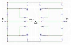
 This is my (after a good sleep) interpretation of
"attaching the Source pins together".
The technique reminds me of the magic resistor in the Monolithic Supersymmetry thread.
However, the value of these R’s has to be much higher: around 10 to 20k.
Any input welcome
/Hugo
"attaching the Source pins together".
The technique reminds me of the magic resistor in the Monolithic Supersymmetry thread.
However, the value of these R’s has to be much higher: around 10 to 20k.
Any input welcome
/Hugo
Attachments
Netlist,
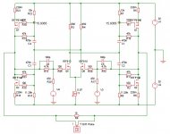
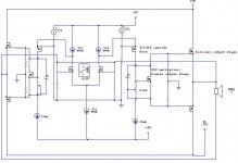
This is a conceptual schematic of what I was talking about. Funny thing about it is that after throwing it together and guessing at the values, I ran the simulation and it worked! 130 watts or so into 8 ohms.
This is only my interpretation of the p-p X amps. In reading about the real thing, I found that Nelson dosen't use feedback around the output stage, so this obviously isn't what he is doing exactly. But, it seems to work, and it's something to look at and think about.
Obviously, when it comes to all of this stuff, it is better to listen to the man himself, than to someone like me who is only beginning to understand the concepts on some basic level. I just thought it was interesting, for the sake of discussion.
Attachments
That's a nice approach, JH.
Your circuit seems to perform quite a bit better than mine except for the harmonic distortion figures.
Again, I have no idea if we're on the right track.
Seeing your design gives me the feeling we are.
Steve
I already simulated your followers yesterday, in silence..of course.
Indeed quite a powerful amp.
I have to take a more in-dept look at it.
Is your last schematic meant to be an X?
Meanwhile the Zen-virus got us again.
Thanks Nelson.
/Hugo
nobody special said:Yes, it's a push-pull X.
I can't see the X. Please tell me.
/Hugo - not that good X-er..
Netlist said:
I can't see the X. Please tell me.
/Hugo - not that good X-er..
Well, the differential pair's current source is the low impedance "summing" point (just like on the AlephX). Since each half of the circuit's voltage amplification stage (which is made up of half the differential and the folded cascode) are inverting, the output of each is fed back to it's own input (look for the resistors at the speaker's + and - terminals going back to the inputs). Do you see it now? In other words, since the output is a follower and is non-inverting, there is no "criss-cross" on the feedback path. Hope this helps.
jh6you said:I would try this concept.

JL6,
would there need to be low value resistors between the sources? (I"m thinking of the monolythic SuSy thread).
You're probably correct about the X.
My understanding is that you mean that since the follower is not inverting the VAS you can't see the X as in an inverting amp.
Suppose you take the feedback from the VAS instead of the output, you could send that feedback resistor to the other side?
I’m I clear and is this more or less correct?
This is what my sim comes up with:
Transfer Function =5.39785e-005
Input Impedance =10450.6
Output Impedance =0.563733
This is with 475ohm input resistors and 4.75k feedback R's.
So, a 10k input impedance isn’t that bad I guess?
I refer to your schematic in post : http://www.diyaudio.com/forums/showthread.php?postid=207343#post207343 but X-ed like the one above in this thread.
/Hugo - master in mixing up threads
Exactly... the Aleph types have an inverting input stage, and the output is also inverting, so you have to take the feedback to the opposite side to get the right phasing. With this, there is only one inverting stage, so you are out of phase on the output, and it can be brought back to the same side... Susy, yes. X, no.Netlist said:You're probably correct about the X.
My understanding is that you mean that since the follower is not inverting the VAS you can't see the X as in an inverting amp.
Not on this amp, because the folded cascode inverts it once. You would have to take it to the same side.Suppose you take the feedback from the VAS instead of the output, you could send that feedback resistor to the other side?
I?m I clear and is this more or less correct?[/B]
Do you know if that is correct? That would be cool, if the input impedance was 10K. But, how could that be?This is what my sim comes up with:
Transfer Function =5.39785e-005
Input Impedance =10450.6
Output Impedance =0.563733
This is with 475ohm input resistors and 4.75k feedback R's.
So, a 10k input impedance isn?t that bad I guess?
/Hugo [/B]
Input impedance is something I need to study more- I don't really know how to calculate it, and what effect feedback has on it.
What simulator are you using, by the way?
nobody special said:
Do you know if that is correct?
Since I don't know either how to calculate the input impedance I have to trust my sim.

The first post from Nelson in the Monolitic SuSy thread says the input impedance is ...well, go and read it.

This is confusing me now, since I don't know if that also applies to this amp.
One of the last versions I made with the LM6181 with 10k input resistors and 100k feedback says 25k input impedance.
According to Nelson's theory it should be 20k, and this amp should be around 1k.
No need to tell you that we should trust Nelson more.
Sim: http://www.spectrum-soft.com/index.shtm
/Hugo
Well, I did a little experiment (and i have no idea if this is right or not, so...)
I looked at the current through the input resistor (using the original values for input and feedback- 475 ohms, 4.75K). I got an approximate value of 3.8mA peak to peak. If you divide the 2 volt peak to peak input signal I was using by this 3.8mA, you get a value of about 526 ohms, which would seem to agree with the article.
When using the potentiometer on the input like in my schematic with the followers, you get anywhere from about 5K to 600 ohms using this method (5K being at minimum volume, 600 ohms being max. and about 3K at mid position). Actually, on that one I inserted a low value sensing resistor in series with the input. I don't know if this is correct or not, but it at least sounds reasonable.
Can anyone here point us in the right direction (direction, direction, direction)
Hi all
Nice with som brainwork!
First, JH´s proposal is the only one which is a true Zen-concept.
But the inefficiency is very low, specially with resistors, because you cant get the full rail swing at the output.
And yes, the impedance should be raised from the about 600 ohm to at least 20K or making a preamp that can dive the 600 ohm load, it is possible.
To measure the impedance, you simply put a resistor in series with the input, then you change its value, until you have have lowered the signal by the half at the node between the testing resistor and the input. Then the inputimpedance is equal to the chosen value of the testing resistor. You can measure the outputimpedance the same way, when a load has forced the amp to deliver half its output max, then the load is equal to the outputimpedance.
A REAL ZEN X
Here's one that should qualify! I also did a version with the Aleph style sources, but couldn't find a way to make them active (I'll have to keep playing with that one.)
On this version, all the mosfets should probably be doubled up to really deliver the power. It is VERY current limited with just a 2 amp source on each end.
- Status
- This old topic is closed. If you want to reopen this topic, contact a moderator using the "Report Post" button.
- Home
- Amplifiers
- Pass Labs
- X-ing Zen V5?