Playing a bit with SJEP120R100 seems to me that warming of a heatsink is much less in comparison to IRFPN150, although both of them were using the same supply power and were put under the same operating conditions (Id = 2A).
According to my understanding, most obviously this is thanks to the superb SJEP120R100 design which proves to be high efficiency and minimal loss devices.")
Really seems that SIC is very promising new technology.
Does anyone playing with SJPE120R100 have similar feelings about thermal power losses?
According to my understanding, most obviously this is thanks to the superb SJEP120R100 design which proves to be high efficiency and minimal loss devices.
Really seems that SIC is very promising new technology.
Does anyone playing with SJPE120R100 have similar feelings about thermal power losses?
The story is replacing Babelfish with Babelfish J2. Heatsinks seems to warm less, now. Searching for the explanation, I found a lot of articles claiming SIC technology advantages in terms of Thermal losses compared to normal Si power Mosfet. Knowing that there are now a number of people that are playing with SJEP120R100, I just wanted to check my observation.
Power dissipation is Pd = Vds x Id no matter what type of FET is used. Given the same operating conditions IRFPN150 and SJEP120R100 will dissipate equally. Difference might appear if transistor start to oscillate or due to unequal thermal resistance of transistor cases.
Talking about Semisouth devices, I’m curious, have you noticed any gate current in idle mode (with no AC signal)? This can be checked by measuring voltage drop across the gate resistor. Will you please check this, I’m curious?
Talking about Semisouth devices, I’m curious, have you noticed any gate current in idle mode (with no AC signal)? This can be checked by measuring voltage drop across the gate resistor. Will you please check this, I’m curious?
Power dissipation is Pd = Vds x Id no matter what type of FET is used. Given the same operating conditions IRFPN150 and SJEP120R100 will dissipate equally. Difference might appear if transistor start to oscillate or due to unequal thermal resistance of transistor cases.
Talking about Semisouth devices, I’m curious, have you noticed any gate current in idle mode (with no AC signal)? This can be checked by measuring voltage drop across the gate resistor. Will you please check this, I’m curious?
Thanks for nice explanation. In the mean time, I understood that I was wrong. Most probably, new liskuns were too fat and temperature measured on heatsink was 42 degree, and measured directly on case of SJEP120R100 was 70 degree. Liskun used now is thinner, and I expect little increase of the heatsink temperature. Also, I checked the Bias, and seems that it is 1,85A instead of 2A. Those two things guided me to have wrong conclusion. Anyhow, I promise to measure voltage over the Gate Resistor in idle mode and will post it here in an hour or two.
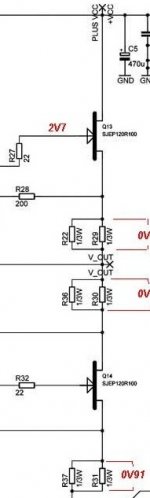
which one 0V3 , which one 6mV ?
V over R32 – 300mV
V over R27 – 6 mV
Attachments
Last edited:
well -now to check the same with spare Babelfish J pcbs ...... and plain IRFPs on output ...
?
I'm finito with measurements
Hm...confused...All gate resistors are 100 Ohms. Measured voltage in idle mode is 300 mV over one gate resistor and 6 mV over the other. Measured on both channels - the same situation - One 300mV, other 6mV.
Thanks for the info. As I suspected looking in the datasheets, power JFETs of Semisouth have peculiar behavior at ‘low’ currents (remember they are primarily designed for high current switching). So at low Vgs (1-1.5V) the gate current is not negligible.
Even more strange is that Ig decreases when Vgs rises, meaning dynamic impedance of the gate is negative. Only at much higher currents Ig starts to rise again and is several tens of mA when Id reaches about 20A (Can’t help recalling Papa’s words that new devices require new approach to get best of it).
I think difference in Ig between devices you’ve measured can be explained with variations of parameters of individual devices and/or difference in operating point as small variations in Vgs can result in significant variations of Ig.
Last edited:
Thanks for the info. As I suspected looking in the datasheets, power JFETs of Semisouth have peculiar behavior at ‘low’ currents (remember they are primarily designed for high current switching). So at low Vgs (1-1.5V) the gate current is not negligible.
Even more strange is that Ig decreases when Vgs rises, meaning dynamic impedance of the gate is negative. Only at much higher currents Ig starts to rise and is several tens of mA when Id reaches about 20A (Can’t help recalling Papa’s words that new devices require new approach to get best of it).
I think difference in Ig between devices you’ve measured can be explained with variations of device parameters and/or difference in operating point as small variations in Vgs can result in significant variations of Ig.
Blagodaram !
No problem - It was a pleasure.
there is certainly a reason why Papa decide to double current through input LTP
so - even without looking at these values ( I confess - I measured gate current during prototyping , but I didn't wrote down , maybe because currents were smaller and pretty same ? ) I wasn't so concerned about SS gate current
edit:
OK - I confess - I'm sloppy - I forgot to write it down .......
so - even without looking at these values ( I confess - I measured gate current during prototyping , but I didn't wrote down , maybe because currents were smaller and pretty same ? ) I wasn't so concerned about SS gate current
edit:
OK - I confess - I'm sloppy - I forgot to write it down .......
I’m considering implications of the negative gate impedance of Semisouth’s. Apparently if they are driven from a hi-Z source the output voltage might reverse the phase. For example, let’s imagine the gate is driven by a current generator. If the generator starts rising the current it will make Vgs *decrease* in order to absorb the current surplus. Consequently, the output voltage rises.
It is hard to determine value of the negative Z from the datasheets. Also apparently it varies significantly with temperature, quiescent current and from individual part variations. Since it is so unpredictable it can’t be easily compensated. Perhaps the best way to cope with it is a brute force low Z diver stage which will drive proper voltage to the gate regardless of the Ig.
It is hard to determine value of the negative Z from the datasheets. Also apparently it varies significantly with temperature, quiescent current and from individual part variations. Since it is so unpredictable it can’t be easily compensated. Perhaps the best way to cope with it is a brute force low Z diver stage which will drive proper voltage to the gate regardless of the Ig.
dunno
less lazy one (than me ) will try to drive it with properly executed follower ........
that means cascoded , CCS loaded bjt or mosfet , temp. compensated ...
it will demand another , more negative rail ..... what is not critical , if using said CCS ;
sky ( or should I say ocean , this time ) is limit
Thanks for the info. As I suspected looking in the datasheets, power JFETs of Semisouth have peculiar behavior at ‘low’ currents (remember they are primarily designed for high current switching). So at low Vgs (1-1.5V) the gate current is not negligible.
Even more strange is that Ig decreases when Vgs rises, meaning dynamic impedance of the gate is negative. Only at much higher currents Ig starts to rise again and is several tens of mA when Id reaches about 20A.
That's interesting. I have tested a lot of R100's and I have
not seen this phenomenon.
Tested at Vds=10v at 1 amp the Gate current is positive
into the Gate (that is to say electrons are flowing from the
Gate). The value ranges from less than 1 uA to as high as
30 uA, typically less than 10 uA. The current is
proportional to the Ids and to the Vds. It increases slightly
with temperature. There is no indication of negative
resistance.
These measurements are DC, but distortion waveforms
in actual amplifiers would reflect this if there was a
dynamic effect.
3 mA Gate current is awfully high for ordinary voltages
and 2A of Ids. I would not consider using such a part,
and likely it is broken.
Kirkwood Rough (Watt Sucking Fireball articles) has
talked to me about potential issues with hot carriers
injection which he indicated was a problem with the
original Vfets of the Yamaha amplifiers of the '70's, and
so I have been on the watch, but have not seen it.
I suggest that you test for Ig as well as Vgs when
matching, which is what I do.
I forgot to ask - where did you see that in the data sheets?
Last edited:
- Status
- This old topic is closed. If you want to reopen this topic, contact a moderator using the "Report Post" button.
- Home
- Amplifiers
- Pass Labs
- Semisouth SJEP120R100 Power Loss