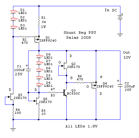
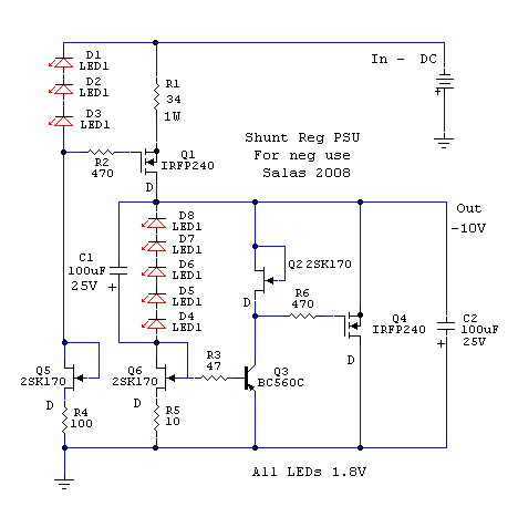
Seems to be the same when it comes to the positive rail. I haven't checked the rest. Neither have I checked if Andrews claim is correct that there should be errors in the schema - it is usable anyway.
Regards
Andrew, the arrows in Q1 and Q2 should be pointing downwards so you were quite right. Now I didn't give the fact much attention since I put it right in my mind and thought.
Since the actual components are FET's the symbols are wrong as well BUT they can be useful for describing the function as is.
BUT my call for help took a totally different direction...
Regards
Since the actual components are FET's the symbols are wrong as well BUT they can be useful for describing the function as is.
BUT my call for help took a totally different direction...
Regards
Last edited:
This schematic is also what Salas posted in another topic. I also built my board by that, so it should be fine. You should check each wire from the board setup to see if really all the components are facing the right way and all wires conenct to the right components.
PS: I guess the system doesn't work well with 1 side partially dead. You'll have to find the dead component, replace and then go on.
R13 has 0,168V dropping, meaning ~17mA if you used 10R. If T6 is a 2sk170, than it is dead for sure (12mA is max for BL).
PS: I guess the system doesn't work well with 1 side partially dead. You'll have to find the dead component, replace and then go on.
R13 has 0,168V dropping, meaning ~17mA if you used 10R. If T6 is a 2sk170, than it is dead for sure (12mA is max for BL).
Last edited:
Thanks mrWagner.
It worked allright for days +9.86V -9.79V but I believe I shorted something poking around measuring. So everything are where they are supposed to be.
V+ still rising... When I first took a reading after the short it was 12.5ish but last evening it was 16.5ish... Very strange.
I have ordered spares.
Regards
Last edited:
That's the schematic I have too, if somebody has a better one, pls post...
That schematic shows two NPN bipolar transistors where P-channel MOSFETs should be, also there are BJTs instead of MOSFET and JFET - quite a mess, I see a lot of white smoke on the horizon...
Last edited:
No I don't have such an annotated file. You can check each fet with the dmm in Ohm mode on pcb when not powered. Each fet should show several decades of Ohm between its outer pins. You can check each bjt with dmm in Volt DC mode when powered, each has to show about 0.6V between b & e pins. You can check each mosfet for 3-4 Volt between g & s pins when powered.
No I don't have such an annotated file. You can check each fet with the dmm in Ohm mode on pcb when not powered. Each fet should show several decades of Ohm between its outer pins. You can check each bjt with dmm in Volt DC mode when powered, each has to show about 0.6V between b & e pins. You can check each mosfet for 3-4 Volt between g & s pins when powered.
Ok, here is my measurements in the schema...
Very kind if you or someone would have a look.
Regards

- Home
- Amplifiers
- Pass Labs
- Mezmerize DCB1 Building Thread


