Hi. I bought a board and because of my lack of experience building diy stuff, I have a few questions about the mesmerize board and the BOM:
1) Can I choose higher wattage audio resistors as long as the R is the same and the tolerance at least as good as the ones listed in the BOM?
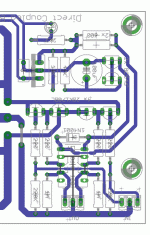
2) The BOM lists two "1R 1/4w metal film 1%". I can't find them on the board... Could someone with better eyes than me show me their location on the board?
3) I want to build a hot-rodded version. I will use the 10R 4w 1% resistors instead of the 68R pair. The board location has three sets of holes, does it matter where the 10R goes? The middle set of holes or it doesn't matter?
4) I would like to take the board to 600ma. Ok for this board? If so, at this level I should use a cooling scheme like Tea-Bag's (http://www.diyaudio.com/forums/blogs/tea-bag/296-salas-dcb1-blue-edition.html)? Or on chip sinks are enough?
My ignorance of the subject matter is probably shining through with some of the questions... Thanks in advance for any help.
higher wattage resistors generally come with higher tolerances.2) The BOM lists two "1R 1/4w metal film 1%". I can't find them on the board... Could someone with better eyes than me show me their location on the board?
3) I want to build a hot-rodded version. I will use the 10R 4w 1% resistors instead of the 68R pair. The board location has three sets of holes, does it matter where the 10R goes? The middle set of holes or it doesn't matter?
you can use 250mW or 400mW or 500mW or 600mW. These all come in 1% E24 values. Check the resistor body length to ensure that when the legs are bent they fit the pad pitch.
The 68r in the standard DCB1 is not 68r.
It is 68//68r giving an effective 34r.
The third hole is left unused in this case.
If you need ~10r then you can use 20//20r (using the two outer holes) or 30//30//30r (using all the available holes). All give the same effective CCS resistance. You might be able to source 1W 30r 1% that fit the pad pitch.
So to get the equivalent of the 10R/5w I could use 3 27R/1w resistors per side? That would be 9R, what kind of mA would the board be at using 9R equivalent resistors? These three individual 1w resistors are equivalent to a single 5w one?
Thanks for the explanations, it's much appreciated.
Thanks for the explanations, it's much appreciated.
Hi,
yes and no.
Use any cheap To92 that has sufficient Ic max. Speed, Vce0 and gain are unimportant in this slow switching application.
Thanks again for your help Andrew. I have been playing with this switching circuit for input selection, and I think I have it working. So far just using one input/output on a scrap of project board; tomorrow I will enable another input and make sure it works as intended.
Initially it did not work at all. I remembered that the data sheet for the flip-flop chip said it needed about 20ns set-up time between voltage being applied to the input pins and the clock pin low-high transition. So I added a small RC network on the clock pin (a small series resistor and a capacitor to ground) and suddenly it worked! Sort of... The transistor would switch off again after about 10 seconds, and it seemed very sensitive (eg., touching the clock pin with a dvm probe would cause the output to go low). Plus, at power-on it was a crap-shoot whether all outputs would be low or all high.
I added a decoupling cap on the power pin of the IC, and added another RC network on the ~CLR pin (to hold it low for a few ms while the chip powered up). I also realized that I hadn't provided a path to ground for the cap on the clock pin to discharge, so added another 10K resistor there. Now it seems to work properly, momentarily closing the switch on the input causes the output to go high, the transistor turns on, and the LED glows (haven't connected a relay yet), and it stays that way even when I poke around with my DVM probe. I'm calling it a qualified success so far! Now I just need to work up a layout for all 6 inputs.
a reminder
http://www.diyaudio.com/forums/swap-meet/177054-omron-g6h-2-12vdc-relays.html#post2361098
I have added to the items I offer for the DCB1. These now include relays, matched strings of leds and a limited number of matched quads of 2SK170BL.
Post in that thread or pm me.
http://www.diyaudio.com/forums/swap-meet/177054-omron-g6h-2-12vdc-relays.html#post2361098
I have added to the items I offer for the DCB1. These now include relays, matched strings of leds and a limited number of matched quads of 2SK170BL.
Post in that thread or pm me.
hi i had build the mesmerize but the first time i run out after 1 30 hour one of the capacitor 4700 and one rectifier mur120 (is that for the relay too) has burn out!!! the temprature on the capacitors both it was very high! and the power supply 50va 2x15v also it was very hot....what can be happen?
hi i had build the mesmerize but the first time i run out after 1 30 hour one of the capacitor 4700 and one rectifier mur120 (is that for the relay too) has burn out!!! the temprature on the capacitors both it was very high! and the power supply 50va 2x15v also it was very hot....what can be happen?
Defective MUR or problematic secondary or a mistake. Measure the trafo alone. If OK, and wiring is OK and caps are correct, use stronger 2A-3A diodes, fuse it, and watch it. In Hypno HR we recommend MUR860 when in hot rod (for going as heavy as inspired) but its also true that many here have the first stage HR on Mez about 180-200mA with the MUR120s working for ages.
hi! ok i rebuild it....i change all mur120 and capacitors 4700 i measure the trafo alone and all numbers was like should be.....after all i run out for 2 hours stand alone the mezmerize and all temprature was ok....probably the problem was defective mur..... thank you salas! hope to cu again on avclub 
DONE!
OK, I finally finished my Mesmerize Blue! For input selection I used a circuit I posted here earlier (thanks AndrewT for assistance), and an Antek xformer (50VA 12V) and Par-Metal chassis. I also got one of those Chinese $10 stepped attenuators, which is remarkably good!
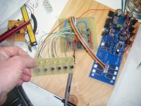
I'm attaching a few pics here. I previously posted photos of the board powered up. When I built my push-button selector I had initially planned for the whole thing to fit behind the front panel, but I couldn't get the layout to fit, so I split it into 2 boards:

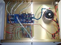
Here is the chassis pretty much wired up. I ran out of my favourite shielded wire, so have only wired 3 of 6 inputs so far.

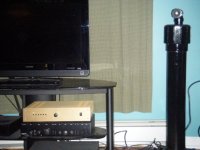
And here is why I built it: last year I built a set of Linkwitz Pluto speakers, but it seemed to me that they were not sounding quite right, and that my "preamp" (pre-outs of an old Arcam integrated amp) was the reason (I don't think the TL072 liked driving long interconnects):

Finally: The sound!
Yes, it makes a difference. Lows frequencies are definitely deeper and tighter, which is interesting because the Pluto eq/xover is AC coupled and has a built-in LF roll-off (15 Hz I think). More importantly, I had felt that the Plutos were missing some high-end "sparkle", which I attributed to some HF roll-off due to cable capacitance and a high-ish output impedance. The high end is back! I probably need to adjust the tweeters down a bit now.
Salas, thanks so much for this design and all your help, and others here (notably St. Andrew) also for the freely offered assistance. This is definitely the best thing I have ever built!
OK, I finally finished my Mesmerize Blue! For input selection I used a circuit I posted here earlier (thanks AndrewT for assistance), and an Antek xformer (50VA 12V) and Par-Metal chassis. I also got one of those Chinese $10 stepped attenuators, which is remarkably good!
I'm attaching a few pics here. I previously posted photos of the board powered up. When I built my push-button selector I had initially planned for the whole thing to fit behind the front panel, but I couldn't get the layout to fit, so I split it into 2 boards:

Here is the chassis pretty much wired up. I ran out of my favourite shielded wire, so have only wired 3 of 6 inputs so far.

And here is why I built it: last year I built a set of Linkwitz Pluto speakers, but it seemed to me that they were not sounding quite right, and that my "preamp" (pre-outs of an old Arcam integrated amp) was the reason (I don't think the TL072 liked driving long interconnects):

Finally: The sound!
Yes, it makes a difference. Lows frequencies are definitely deeper and tighter, which is interesting because the Pluto eq/xover is AC coupled and has a built-in LF roll-off (15 Hz I think). More importantly, I had felt that the Plutos were missing some high-end "sparkle", which I attributed to some HF roll-off due to cable capacitance and a high-ish output impedance. The high end is back! I probably need to adjust the tweeters down a bit now.
Salas, thanks so much for this design and all your help, and others here (notably St. Andrew) also for the freely offered assistance. This is definitely the best thing I have ever built!
Parts
I noticed that a lot of posts to this topic and, especially, the Hypnotize Hot Rod thread, are about parts selection. I am very pleased with my Blue Mez build, and thought I would note some of my parts choices and reasons. Keep in mind that I am making NO claims that my selections are better or worse than any one else's, and there are a few choices I might re-think if I had to do it again, and some choices I made simply because the parts were "good enough" and "there".
I was lucky enough to find another user on this forum who was selling an unpopulated Blue Mezmerize board and 7 relays (12V) at a good price, so I didn't have to wait for a group-buy.
I bought a Schaffner FN9222R-1-06 power entry module from Mouser, wired to an Antek 15Vx2 50VA transformer. If the 30VA unit was significantly cheaper or physically smaller I probably would have got that.
For a volume control I used one of these: DACT Type 21 Stepped Attenuator / Volume 20K for PreAmp | eBay I hate that they call it a "DACT-type stepped attenuator", because of course it has nothing to do with Danish-made switches. It's a stepped attenuator that uses 1% tolerance SMD resistors, and it seems pretty OK for $10!
I got 2 pairs of matched JFET's from one of the suppliers here, "Blues".
The Mouser search page is unpredictable, and when I searched for 2SK170's (unmatched) it told me they were out of stock, so I did a little Googling around. I found a place called Audio Lab of Georgia which had a good selection of parts at decent prices and ordered some JFET's, MOSFET's , diodes, and 12V regulators from them. Unfortunately, while they had 2SK170's, for MOSFET's they had IRFP240's and IRFP9140's, so those are a bit un-matched for me. After I had placed the order I searched again on Mouser and saw they had rafts of the 2SK170's in stock... I'm glad to spread my business around, but when I have to pay shipping on every order...
For the big 4700uF caps I used Panasonic EEU-FC1E472; when I had searched a few days earlier there were some higher-value caps with the same diameter and lead spacing, but when I ordered I couldn't find any low ESR, high temp (105C) caps with a higher capacitance.
For the caps across the group of 5 LED's, I used Panasonic FR 820uF 35V (105C). For the regulator output caps I used Panasonic FM 100uF 50V.
For current-setting resistors I used Vishay RN65's. These were 0.5W 0.1% tolerance parts. That close tolerance is probably silly for that application, but I had some vague idea in my head to keep currents balanced among the resistors, and equal on each rail (which won't happen), and I wanted a low noise, low TCR (25ppm) part. The only values I could find in the right range were 61.9 ohms. I used 3 of those per side, so a baby "hot-rod" at about 80mA per rail.
Most of the resistors I used were IRC RC55's, tight tolerance, low noise, low tempco metal films, mostly 0.1% tolerance / 25ppm. Instead of 220R I use 221R because that was what was available; likewise 221K. I couldn't find 1M RC55's, but I found Vishay PTF651's at that value, again 0.1% tolerance and very low noise, and also only 5ppm tempco! An extravagance at over $2 per, but I only needed 2 of them.
For 470R base-stopper resistors I used IRC carbon composition RC20's, 5% tolerance, no noise figures, but the only carbon comp resistors I could find that even specified a tempco (not impressive at 150ppm, but better than some carbon films at 300ppm).
I think everything else was pretty much per the BOM, except my custom push-button switch.
Oh, wire: I used some nice shielded wire I got a while ago from Apex Jr.Home Page, stranded silver-plated copper, teflon insulation, and I think $0.25/ft. Unfortunately I ran out after wiring the volume control, the outputs and 3 inputs. Not sure what I will use for the other 3 inputs, I am considering some old 10base2 ethernet coax I have lying around. For non-signal hook-ups I used non-shielded wire from the same source, also stranded silver-plated copper. For jacks I used Neutrik NYS367's from Mouser.
That's all I can think of for now.
Last edited:
- Home
- Amplifiers
- Pass Labs
- Mezmerize DCB1 Building Thread
