Vf is the voltage drop across the LED when forward conducting at the current specified by the manufacturer.
7.5V must surely be the voltage across the 1k0 resistor.
That tells you that the test current is 7.5mA (+-resistor tolerance +-meter tolerance +-temperature effects) and the corresponding Vf that still needs to be measured.
Do not rely on an answer that is the difference between two similar value measurements, unless there is no better way to get a result.
I have red LEDs which vary in Vf from 1.55V to 1.95V at the same current. Changing the current can expand that range from 1.5V to 2V
It depends on the LED manufacturing process and the tolerance intrinsic to that process.
Last edited:
Hi all.
I ve been reading the threads on how to build/and hotrod a board for some time now and i want to be sure i got it right.
So bear with me once again and confirm or correct me if i am wrong.
Building a Mesmerize board using the values suggested on board gives a standard version running on 60mA.
For the standard version a 12v or a 15v / 50-100 VA transformer can be used, 15v being better if one wants to hotrod.
In order to hotrod, 3*68 Ohm resistors can be placed resulting to somewhat 90mAmps. In order to go to 200 mA, one needs to install 1*10Ohm/5 W resistor or 3* 30Ohm ( or value close to that )/ 2-3 W resistors. Paralleled resistors give the advantage of better dissipation.
Lowering the resistors value below 10Ohms results to more Icss.
Up to 600 mA the use of MUR120 is ok ( why not 1A which is the diode limit? ) but would be better if replaced with 840 or 860. Irfps need to be sinked good.
Replacing the PScaps from the standard value to something bigger is good but not mandatory for hotroding. If memory serves my right the 4700μF caps can do good for up to 600 mA.
One thing i dont get for sure though is from up to what value do the MUR's ( 840/60 ) need sinking? Or dont they need?
To sum up:
Populating the board with the values suggested on it, gives a standard version running at 60mA
Populating the board for having, let's say 200 mA ICCS, things that need to be done are -
1. Replace the PS resistors with 1*10R/5W or 3*30R/2-3W
2. Better sinking for the irfps
3. Not necessarily, replace the MUR120 with 840/60.
4. Not necessarily, replace the PS caps with something bigger.
Do i forget something here? Have i got anything wrong?
Regards
Last edited:
I read somewhere on the DCB1 Blue Hypno thread, that the MUR860's were good up to about 300mA without heatsinking. I don't have the link, but go do a search on that thread, and you should find it.
I'm in the process if building my Blue Mez with 2 x 20ohm 2W resistors in place of the 68 ohm ones (per Tea-Bag's recommendation). This gets you in the range of the "standard" hot rod from what I understand.
I'm in the process if building my Blue Mez with 2 x 20ohm 2W resistors in place of the 68 ohm ones (per Tea-Bag's recommendation). This gets you in the range of the "standard" hot rod from what I understand.
Vf is the voltage drop across the LED when forward conducting at the current specified by the manufacturer.
7.5V must surely be the voltage across the 1k0 resistor.
That tells you that the test current is 7.5mA (+-resistor tolerance +-meter tolerance +-temperature effects) and the corresponding Vf that still needs to be measured.
Do not rely on an answer that is the difference between two similar value measurements, unless there is no better way to get a result.
I have red LEDs which vary in Vf from 1.55V to 1.95V at the same current. Changing the current can expand that range from 1.5V to 2V
It depends on the LED manufacturing process and the tolerance intrinsic to that process.
Yes, the voltage reading is across the resistor as stipulated by various build threads that show this method.
However what you are saying is that the current I have is not the same as the current in the actual application, hence the higher voltage value. That makes sense.
I need to go through the original DCB1 thread as I know there was reference to measuring the LED's at a current value similar to the application.
Thanks
90mA per rail then. How is you output DC offset?
L=0,1mV
R=-0,8mV
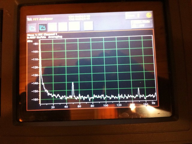
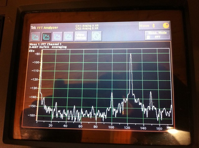
I did a noise test of the power supply
DCB1
7812
Last edited:
Here is such a thread. Merged.
Thanks! I think I read this thread before, then couldn't find it the other day, which I attribute entirely to my mind slipping. Don't get old...
Are the switches mechanically ganged to keep from enabling more than one input at a time?
Well, first of all, there no actual switches at all, I'm just spit-balling.
")
But you have identified one definite bug in that design (or maybe it's a "feature"). If 2 switches are closed simultaneously (within a few nanoseconds) it should turn on 2 inputs. I don't see that as huge problem, because (1) it is unlikely, I think it would actually be difficult to close 2 switches within the right time window, and (2) a press of a single button would fix it. If I implement the indicator LED part, then there would be a visual indicator if 2 inputs were selected.
I don't like physically ganged switches, and in this circuit (as I imagine it) the switches are momentary-contact, not radio-buttons (for those of us who remember radios with mechanical presets, as opposed to something in a UI design). There should be a logical circuit which would prevent selecting more than 1 input at a time, perhaps leveraging the "clear" pin. IIRC the clear pin sets all outputs low regardless of the state of inputs and clock. So what logic circuit would say "if more than 1 output is selected then assert the clear pin"? A six-way NAND?
For that matter I have also not addressed what happens at power-on. Should all relays be open until an input is selected? Should there be a default input selected? I can't conceive of a way to preserve state across power cycles.
Thanks for making me think, please let me know if you have other concerns or ideas.
Hi Andrew, thanks for the detailed reply. I intend to use a 12V regulator on the Mez board and 12V relays (already have them). My earlier comments about power referred to powering the logic chip and its inputs. Either way I will steal some output from the 12V reg on the Mez board for the switch board, but I can either power the chip at 12V or add a 5V regulator on the switch board to power the chip and provide input to the switches. Probably a TO92 regulator would be fine.
Yeah, I like that idea too, haven't seen the right switches yet. If I can't find a light-up switch then an LED adjacent to the switch would be OK.
So how much current does an average LED need for average brightness? The rated coil current for the relay is 11.7mA, which I would not have thought excessive for some LED's, but then I really don't know. As for the voltage, while you are absolutely correct, I think the relays I have (ATQ203) will operate at 9V which gives me a couple of volts in-hand to play with; I think I should be able to find LED's with Vf about 1.6-1.7V. So that might work without messing with the regulator on the Mez board. OTOH, replacing the 7812 with an LM317 and a couple of resistors should be trivial.
Must it?Couldn't all 6 LED's share a common power source but be individually switched on by their associated transistor? That is, the coil circuit and an LED-resistor circuit each connecting to the collector of the transistor? Of course then the transistor needs to pass the coil current (12mA) plus the LED current (??mA), but that shouldn't be an issue.
Excellent, thanks. This was very much a back-of-the-envelope sketch, I included emitter resistors as a matter of form thinking I might need to limit current somehow. Of course, since a mechanical switch would connect the relay directly to ground, that seems unlikely to be needed!
Thanks again for the comments, much appreciated.
I love the idea of "press the selector button" and the LED confirms the selection. It would be even better if the selected button lit up, (a push to make button with a LED inside).
Yeah, I like that idea too, haven't seen the right switches yet. If I can't find a light-up switch then an LED adjacent to the switch would be OK.
The LED could replace the emitter resistors R12 to R18, but then the supply voltage would need to be raised by ~2V to either 7V or 14V. This series LED would pass the same current as the relay coil. It will be very bright. Adding a resistor bypass across the LED will adjust the brightness.
So how much current does an average LED need for average brightness? The rated coil current for the relay is 11.7mA, which I would not have thought excessive for some LED's, but then I really don't know. As for the voltage, while you are absolutely correct, I think the relays I have (ATQ203) will operate at 9V which gives me a couple of volts in-hand to play with; I think I should be able to find LED's with Vf about 1.6-1.7V. So that might work without messing with the regulator on the Mez board. OTOH, replacing the 7812 with an LM317 and a couple of resistors should be trivial.
If instead the LED is placed in parallel, then it must be in parallel with the relay. That involves 6 extra wires tapping into the PCB.
Must it?Couldn't all 6 LED's share a common power source but be individually switched on by their associated transistor? That is, the coil circuit and an LED-resistor circuit each connecting to the collector of the transistor? Of course then the transistor needs to pass the coil current (12mA) plus the LED current (??mA), but that shouldn't be an issue.
Those emitter resistors are not required.
Excellent, thanks. This was very much a back-of-the-envelope sketch, I included emitter resistors as a matter of form thinking I might need to limit current somehow. Of course, since a mechanical switch would connect the relay directly to ground, that seems unlikely to be needed!
Thanks again for the comments, much appreciated.
L=0,1mV
R=-0,8mV
I did a noise test of the power supply
Nice results. Your build seems fine.
I need to go through the original DCB1 thread as I know there was reference to measuring the LED's at a current value similar to the application.
Thanks
Hook up a 2SK170 Drain side to battery + (even better use the one destined to feed each leds row on final board). Connect its G,S together. From G,S connect a led's anode, connect its cathode to battery -. That way you can measure Vf across each led on actuall current it will see in circuit. Note them down and assemble reasonably matching string pairs.
when using a bjt as a switch, aim for hFE ~10 which puts the device into saturation and ensures the Vce is very low (~0.1V) This stops the bjt heating significantly.
The base current must be limited by that base stopper, so the [base supply voltage - base voltage] / [base stopper value] ~= Ic/10
eg.
if the base sits at Vf + Vbe above ground ~2.4V
and Ic~13mA
and Vbase supply = 5V (from the digital chip)
Then 0.013/10 = 5-2.4 / Rbs
Base stopper required would be ~2k (from rearranging to give Rbs=[5-2.4]/[0.013/10]
now to the LED bypass resistor.
most LEDs when viewed indoors look bright enough with 2mA to 5mA.
Let's take the higher value to start, because the modification to reduce brightness is very easy.
Vf of the LED @ 5mA ~ 1.7V
current to bypass is 13-5 =8mA = 0.008A
Rbypass = Vf / Ibypass = 1.7 / 0.008 = 220r.
If this is too bright then add a second resistor in parallel, try 470r or 300r or 270r.
You can leave the second parallel resistor in place or you can replace the pair with an equivalent resistor for your selected brightness. You can even make the second resistor selectable with a jumper for users who want different brightness.
yes, just tap off a single supply voltage and insert a dropping resistor to feed all 6 LEDs. I knew someone would see a better way.Couldn't all 6 LED's share a common power source but be individually switched on by their associated transistor?
Last edited:
Thanks Salas, I've done what you suggested and am now getting sensible results (but I also realised I wasn't measuring correctly last night - it's been a long week!!).
Now I'm getting consistent Vf of 1.74 on the LED's so that would give me 8.7V for Vref and 5.22V for CSS. I think those voltage numbers are close enough to the 9V and 5.4V recommended, but if anyone thinks otherwise then please advise.
Thanks
Now I'm getting consistent Vf of 1.74 on the LED's so that would give me 8.7V for Vref and 5.22V for CSS. I think those voltage numbers are close enough to the 9V and 5.4V recommended, but if anyone thinks otherwise then please advise.
Thanks
[snip]when using a bjt as a switch, aim for hFE ~10 which puts the device into saturation and ensures the Vce is very low (~0.1V) This stops the bjt heating significantly.
Wow, thanks once again for such a detailed reply! I think I am now leaning toward the parallel-LED approach, just to be sure there are no issues with the relay coils. So I will ditch the emitter resistors, and with the hints you have provided start filling in some values. This might actually work!
Bill
After I heard the weekend the DCB1, I'll want to go to a full Hod Rod (First stage).
I have a few questions (200mA Hot Rod): 5w or 6W 10ohm wirewound resistors are ok or I need get a metal resistors? (Low inductance), the MUR120 are ok for the 200mA?, will be my chassis enough for dissipate the heat?.
I have a few questions (200mA Hot Rod): 5w or 6W 10ohm wirewound resistors are ok or I need get a metal resistors? (Low inductance), the MUR120 are ok for the 200mA?, will be my chassis enough for dissipate the heat?.
hot rodded mesmerize
Trying to decide on what board to buy from the latest GB, so:
From what I understand/read, the mesmerize standard version runs at 60 mA - has anyone built a hot-rodded version (of the mesmerize) that runs at 600 mA or close to that?
Thanks
Trying to decide on what board to buy from the latest GB, so:
From what I understand/read, the mesmerize standard version runs at 60 mA - has anyone built a hot-rodded version (of the mesmerize) that runs at 600 mA or close to that?
Thanks
Since you only got 1.55V average across your setting resistors, use 8R2 5W to near 200mA, any type your heart desires. Non critical. MUR120 have taken 200mA reported builds enough times in the black PCBs original building thread.
Trying to decide on what board to buy from the latest GB, so:
From what I understand/read, the mesmerize standard version runs at 60 mA - has anyone built a hot-rodded version (of the mesmerize) that runs at 600 mA or close to that?
Thanks
Someone did it and it was on a flimsier black board if I remember well. Maybe it was a Hypno, but still black first run, equivalent. Don't go that high, its not like the Hypno Blue with its more filter caps, space for fat setting resistors, bigger diodes etc. 200-300mA will play very well.
Am i correct in assuming the matched SK170's are located next to the BC550 and BC560's>
Thanks
The must be matched are where it says 4x2SK170. Those are the audio fets. The others are PSU.
Thanks Salas - As for matching, I want to check my understanding of this too.
My understanding is that each pair of SK170's should have the same Idss, but the two pairs do not have to have the same Idss as each other, although it is good to get the Idss of each pair as close to each other as possible.
This part of the build has always confused me, but I'm trying to learn.
Thanks
- Home
- Amplifiers
- Pass Labs
- Mezmerize DCB1 Building Thread