but is there a complete circuit of the Mez somewhere with part designations which relate to the PCB?
The boards have no designations like R1, R2 etc but they have the actual component values and semiconductor types printed. So its tell tale what goes where.
Attachments
hey all, I'm about to put in my order for some mez parts but have 1 question. I intend to hotrod mine a little bit, so I'm going to get some 6.2R wirewound resistors (for a little over 300ma current) but will the 120 diodes be ok? I was going to order some mur860 or stealths but I would have to bend the pins to make them fit the mez board since they are to-220 trying to fit into a do-41. Should I do this? or can I safely hotrod the mez with the 120s? does the "ultrafast" recovery time make that much of a dif?
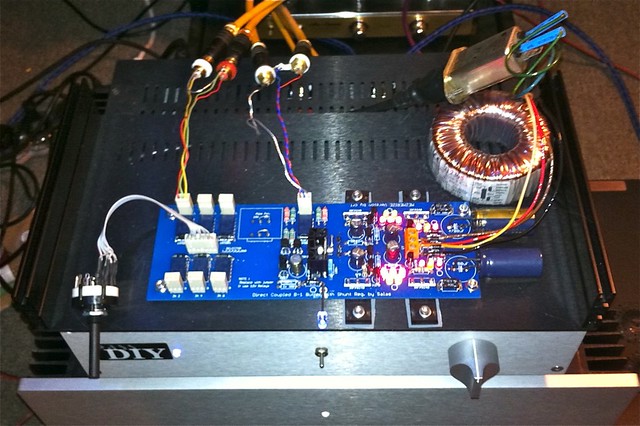
I'm listening the DCB1 Mezmerize, great sound, a clean and very open stereo image. I have a bit of hum when my ear are close to a speaker (My speakers have 96dB 1W/1m), but is a very provisional installation without pot (Just a jumper) and fair wires, I'll try to find the hum when I have really finished the DCB1.
In other hand, I'm thinking in hot rod a bit my unit, simply by adding up to two 68 Ohm resistors more in parallel with the existing ones (Now two of 68 Ohm 1W). what is the good mA value for the DCB1? what is the safe value for the stock diodes (MUR120)?.
Best Regards
In other hand, I'm thinking in hot rod a bit my unit, simply by adding up to two 68 Ohm resistors more in parallel with the existing ones (Now two of 68 Ohm 1W). what is the good mA value for the DCB1? what is the safe value for the stock diodes (MUR120)?.
Best Regards
The diodes you got have 1A nominal spec. It depends on your sinks where you can go. Can I see a picture to estimate? Congratulations by the way. Tiny hum you will solve. There is no issue when you will ground well and keep the Tx away from the inputs. Even on FFT. We also know from members feedback in systems with horns etc.
Mezmerize build
Hi:
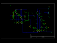
Sorry if this is in the wrong place for this post, I can't find a thread dedicated to building the Mesmerize. I am getting ready to build one, but I have an itch to use something other than a rotary switch to activate the input relays. I have always liked momentary-contact pushbuttons a la Quad 34/44 preamps. So, without really knowing what I'm doing I came up with the following circuit. I would appreciate some feed-back, like for example "that won't work" or "that might work" or even "there's a much better way to do that".
First let me apologize for the graphic, I just downloaded the geda schematic editor and this is my first time using it.
The circuit uses a 40174 hex D-type flip-flop. Each switch is connected on one end to a voltage source. (The 4000-series chips can use up to +15V supplies so I am thinking I will just steal some +12V from the regulator on the pre-amp board; alternatively I could add a 5-volt regulator.) When, for example, SW1 is closed it applies a high voltage to input D1, and also to the CLOCK input (through a diode to insulate it from the other inputs). The low->high transition on the CLOCK line causes output Q1 to go high, which drives transistor Q1 through a base resistor. The transistor switches on, and completes the circuit from input 1 on CONN1 (coming from relay coil) to ground through pin7 on CONN1. (Yeah, I know I have an extra ground symbol there.) When another switch is closed, output Q1 will go low and the other output will go high.
One concern I have i that, at least on paper, the chip needs a few nanoseconds of set-up time between a change on the inputs and the transition on the clock line. I figure a small RC circuit on the clock line could introduce a small delay, with maybe a series small-signal diode that wouldn't conduct until the voltage reached Vf. I think it would just need a few pF and a small resistor for the delay (10 or 20 nS should do it).
Does this look like it would work? If so, I also want to include indicator LED's; should they be in series with the relay coils or parallel? I think this could easily be built on a piece of veroboard, perhaps with the switches and LED's on the back to mount to a front panel.
Any and all feedback appreciated.
Hi:
Sorry if this is in the wrong place for this post, I can't find a thread dedicated to building the Mesmerize. I am getting ready to build one, but I have an itch to use something other than a rotary switch to activate the input relays. I have always liked momentary-contact pushbuttons a la Quad 34/44 preamps. So, without really knowing what I'm doing I came up with the following circuit. I would appreciate some feed-back, like for example "that won't work" or "that might work" or even "there's a much better way to do that".
First let me apologize for the graphic, I just downloaded the geda schematic editor and this is my first time using it.
The circuit uses a 40174 hex D-type flip-flop. Each switch is connected on one end to a voltage source. (The 4000-series chips can use up to +15V supplies so I am thinking I will just steal some +12V from the regulator on the pre-amp board; alternatively I could add a 5-volt regulator.) When, for example, SW1 is closed it applies a high voltage to input D1, and also to the CLOCK input (through a diode to insulate it from the other inputs). The low->high transition on the CLOCK line causes output Q1 to go high, which drives transistor Q1 through a base resistor. The transistor switches on, and completes the circuit from input 1 on CONN1 (coming from relay coil) to ground through pin7 on CONN1. (Yeah, I know I have an extra ground symbol there.) When another switch is closed, output Q1 will go low and the other output will go high.
One concern I have i that, at least on paper, the chip needs a few nanoseconds of set-up time between a change on the inputs and the transition on the clock line. I figure a small RC circuit on the clock line could introduce a small delay, with maybe a series small-signal diode that wouldn't conduct until the voltage reached Vf. I think it would just need a few pF and a small resistor for the delay (10 or 20 nS should do it).
Does this look like it would work? If so, I also want to include indicator LED's; should they be in series with the relay coils or parallel? I think this could easily be built on a piece of veroboard, perhaps with the switches and LED's on the back to mount to a front panel.
Any and all feedback appreciated.
Attachments
Last edited:
Hi,
The power feed to the selector relay comes from the same resistors that feed the mute relay.
If the regulator voltage is selected to match the relay voltage then these resistors are linked across (0r0). It will work fine.
If you use a higher voltage regulator than the relay is rated for, the resistors are used to drop the excess voltage.
If a second relay is brought "ON" it will drop the voltage applied to the "newly" selected relay even further and the newly selected relay might not trigger. The existing mute relay will not drop out due this voltage sag. There is a PCB mod that can overcome this (no details just yet)
This effectively means use 12V reg + 12V relays
or
use 5V reg + 5V relays.
I would stay with the 12V option for everything.
I love the idea of "press the selector button" and the LED confirms the selection. It would be even better if the selected button lit up, (a push to make button with a LED inside).
The LED could replace the emitter resistors R12 to R18, but then the supply voltage would need to be raised by ~2V to either 7V or 14V. This series LED would pass the same current as the relay coil. It will be very bright. Adding a resistor bypass across the LED will adjust the brightness.
If instead the LED is placed in parallel, then it must be in parallel with the relay. That involves 6 extra wires tapping into the PCB.
Neither way is brilliant, but both can be done.
Is there a third way?
Those emitter resistors are not required.
Last edited:
The way you use the chassis as a sink you can go 4x68R no problem. That will be about 120mA, but check the drop across the resistors for trimming current more equally between polarities. It usually differs. You can even go near 200mA and it will sink OK. ICCS=VRset/Rset.
I did a small hot rod
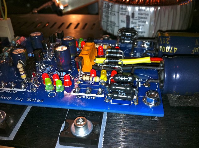
Voltage drop across R= 1,57V and 1,53V.
R= 17,4 Ohm and 16,9 Ohm.
I did a small hot rod
Voltage drop across R= 1,57V and 1,53V.
R= 17,4 Ohm and 16,9 Ohm.
90mA per rail then. How is you output DC offset?
Hi:
Sorry if this is in the wrong place for this post, I can't find a thread dedicated to building the Mesmerize.
Here is such a thread. Merged.
The spec of the Omron relays has a coil resistance of 1028 ohm, but can the resistance be less? The specified Omron relays aren't available in the UK, but there are others, including some with coil resistance of 720 ohms that I have the chance to buy at a good rate. Can I use these lower resistance relays?
Thanks
Thanks
the coil resistance is not critical.
The pin layout must be identical, note that 2pins are not connected and thus do not need to exist on the replacement.
The contacts and the audio route through the relay should be similar for audio quality. I have no idea how you check that.
Only the mute relay and one other are active during operation.
12Vdc + 720r coil gives a current consumption of ~33mA, not a problem.
I've just started to measure some LED's based on the method of a 9V battery and a 1K resistor, but my Vf on the 1.8V leds I have is around 7.5 to 7.4V. If I deduct 7.4 from 9 that gives me 1.5V, but that's pretty poor compared to the marketed 1.8V.
And these LED's are the Mouser items referenced on the BOM.
Also, I've seen build thread pictures where they've measured 1.9V using the method above (9v battery and a 1K resistor), so how come I'm seeing approx 7V on my meter?
Thanks
And these LED's are the Mouser items referenced on the BOM.
Also, I've seen build thread pictures where they've measured 1.9V using the method above (9v battery and a 1K resistor), so how come I'm seeing approx 7V on my meter?
Thanks
- Home
- Amplifiers
- Pass Labs
- Mezmerize DCB1 Building Thread