LED matching: You want the group of 5 and the group of 3 to each be as close as possible to the target voltage in the build guide. The individual LED Vf doesn't matter, just the groups.
So the sum of the Vf for the group (of 3 or 5) is what's important? What are the target voltages, or where is the build guide?
Only important thing is you end up with less than 5mV DC offset across the audio outputs. And that is mainly a matter of how close those four JFET guys near the output relay pair together. Pay fair attention to have same number groups of reds that read close in total string voltage. DMM will show less than in circuit Vf in each LED bcs it feeds very little current to save battery. If they average 1.8-1.9V at 5-7mA they are fine. Wanna check that better? Get a 9V bat and light them up through 1K resistor in series, measure VDC across each. Note them down on a piece of paper and lay them next to their numbers. Then pick em up and combine them using a pocket calculator for expected totals first.
This should be obvious but I'm just not understanding.Only important thing is you end up with less than 5mV DC offset across the audio outputs. And that is mainly a matter of how close those four JFET guys near the output relay pair together. Pay fair attention to have same number groups of reds that read close in total string voltage. DMM will show less than in circuit Vf in each LED bcs it feeds very little current to save battery. If they average 1.8-1.9V at 5-7mA they are fine. Wanna check that better? Get a 9V bat and light them up through 1K resistor in series, measure VDC across each. Note them down on a piece of paper and lay them next to their numbers. Then pick em up and combine them using a pocket calculator for expected totals first.
I measured all 50 with a 9V and 1K resistor in series, wrote down numbers and grouped like-values. I'd have to go find the paper but, if I'm remembering correctly, near every LED measured 1.74V, varying only in the thousandths digit. What are the expected totals (sum of the group?) I should be shooting for?
Again, I apologize if this has been answered but I'm not grasping the answer and want to make sure I do this correctly.
If you have any suggestions from mouser, I'm placing an order soon.9.4V for quintets 5.64V for triplets. You got wimpy reds. Try mix some greens or yellows.
that is the maximum continuous that should not blow up the LED in the specified lifetime.True. It's funny how most LEDs are spec'ed at 20mA, but you would never want one that bright!
Most will operate the LED at 10% to 50% of the maximum.
that is the maximum continuous that should not blow up the LED in the specified lifetime.
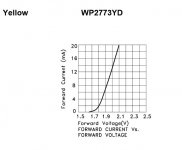
Not as a rule. Take a look at the data sheet for the LED Salas referred to above, for example (Mouser part number 604-WP2773YD, Knightsbridge WP2773YD). Specs like dominant wavelength, spectral half-line width, Vf, etc are specified at If=20mA. However, the maximum DC If is 30mA, and peak If is 140mA (duty cycle 1/10, pulse width 0.1ms).
Most will operate the LED at 10% to 50% of the maximum.
That's why I pulled 10mA out of my nether regions (50% of nominal), but as Salas pointed out even that is probably too bright for a panel in an average room.
9.4V for quintets 5.64V for triplets. You got wimpy reds. Try mix some greens or yellows.
I'll try ordering 50 of the yellow LEDs you suggested, measuring, then mixing in with the reds. I took a look at my notes and all the LEDs ranged from 1.73 to 1.744, the bulk being around 1.73 V. I ordered 50 Kingbright reds from Mouser, P/N WP710A10SRC/E. Looking at the datasheet, unless I'm reading something wrong, Vf is listed at 1.85-2.5V. Mine are nowhere close to that. Did I do something wrong with my measurement? Here is what I did. 1) Fresh 9V battery. -V to Cathode of LED. 2) From +V, I attached a 1K resistor in series, the other end to the Anode of LED. 3) With LED lit, I set my DMM to VDC, ran pos. lead to Anode, Neg. lead to Cathode and noted the measurement. I could understand a few out of spec, but all 50? Surely I screwed something up.
1.73 to 1.74 seems pretty darn close standard deviation.
The range in their spec sheet is usually far wider than production.
Kingbrights generally have nice tight tolerances. If you need to get a little stronger voltage, a couple of green kingbrights will do good.
OK, I'm ignorant AND Mouser illiterate. Any suggestions for greeen Kingsbrights from Mouser would be great. Might as well add some more things to my BOM. It's only money, right?
") At least the board will look cool. Like a mine Fremont Street.
At least the board will look cool. Like a mine Fremont Street.Using K170BL under 0.6V Vbe of the BC550/BC560 will lose about 18% of its IDSS. You will mostly chance on BL 7-9mA when populating the regs area randomly. You may want loosely match a pair for those positions, no problem. Say you end up with 6.5mA running in both strings (takes the leg trick to do that in a Mez also, read a few pages back #1361). Look at this attached chart now. At such current the model I suggested gives a hair below 1.9V. You want dead on 10V? 10V-Vbe (0.6V)=9.4V/5=1.88V. You want 200mA? Each IRF will likely produce VGS between 3.5-3.7V. 3*1.88=5.64V 5.64-3.6=2.04V over Rset 10R 2V/10R=200mA. You don't need 50 as they are usually much consistent, but hey save some for other projects.
Bottom line:
Its nice to have V targets and matches but in DCB1 its not make or break. Still its a nice feeling to read equally.
Bottom line:
Its nice to have V targets and matches but in DCB1 its not make or break. Still its a nice feeling to read equally.
Attachments
dodog:
You don't need to over-think this. Using the recommended parts will yield a working preamp.
However, look at the graph Salas posted. We are running the LED's at a few mA, so they are going to have a Vf that is lower than spec (which is @20mA).
Look at the curve Salas sent to understand the V/I relationship of an LED.
"Not as a rule"?Not as a rule. Take a look at the data sheet for the LED Salas referred to above, for example (Mouser part number 604-WP2773YD, Knightsbridge WP2773YD). Specs like dominant wavelength, spectral half-line width, Vf, etc are specified at If=20mA. However, the maximum DC If is 30mA, and peak If is 140mA (duty cycle 1/10, pulse width 0.1ms).
That's why I pulled 10mA out of my nether regions (50% of nominal), but as Salas pointed out even that is probably too bright for a panel in an average room.
If it's a 20mA LED, then it's not a 30mA LED.
Nor is it a 15mA LED.
If it says 20mA, it means 20mA continuous duty.
If you want to use non continuous duty, then the datasheet usually shows how to calculate the maximum allowed.
yes, you screwed up.I'll try ordering 50 of the yellow LEDs you suggested, measuring, then mixing in with the reds. I took a look at my notes and all the LEDs ranged from 1.73 to 1.744, the bulk being around 1.73 V. I ordered 50 Kingbright reds from Mouser, P/N WP710A10SRC/E. Looking at the datasheet, unless I'm reading something wrong, Vf is listed at 1.85-2.5V. Mine are nowhere close to that. Did I do something wrong with my measurement? Here is what I did. 1) Fresh 9V battery. -V to Cathode of LED. 2) From +V, I attached a 1K resistor in series, the other end to the Anode of LED. 3) With LED lit, I set my DMM to VDC, ran pos. lead to Anode, Neg. lead to Cathode and noted the measurement. I could understand a few out of spec, but all 50? Surely I screwed something up.
The Vf is dependant on the current and the temperature.
The manufacturer usually specifies the current and the temperature for the specified Vf.
If you change one or both of the operating conditions then you will not replicate the specified Vf.
the output relay problem
Hi Salas,
it's my first post here. Yesterday I solded the firs board and had the known and descripted problem with output relay (it doesn't run).
It seems to be a "german problem", most members with this problem wrote from germany??
I use BC517 and BC550. Transistors checked with peak atlas, decouplings (100nF and 150nF beside 7812 and BC 517) installed, resistors checked, voltage is fine (12,7V), input relay (12V) is running.
And now a phenomen: if i touch the base of 517 with my finger, the relay is running, but voltage about N4001 starts with 12V and slow down to 1,2V in a few seconds. I don't understand: what's happening there?
Must I use the Z-diode bypassing the BC550? Or do you know a trick, starting and running the output relay serious?
Many thanks
Meinolf
Warmer sound
Hi Andrew,
No clue what 2nd harmonics do. I only know what kind of sound I like
So, the original sounded a little metalic to me. Changed the resistors and mildly hotrodded it. Just to compare. This just sounds better to me and that is why I DIY, to be able to fiddle around with specs so I like the sound
I am interested in learning more about harmonics... I guess I'll get around to that someday
Why do you want to modify the output to sound Warm?
Are you referring to extra 2nd harmonic distortion?
Hi Andrew,
No clue what 2nd harmonics do. I only know what kind of sound I like
So, the original sounded a little metalic to me. Changed the resistors and mildly hotrodded it. Just to compare. This just sounds better to me
and that is why I DIY, to be able to fiddle around with specs so I like the sound I am interested in learning more about harmonics... I guess I'll get around to that someday
- Home
- Amplifiers
- Pass Labs
- Mezmerize DCB1 Building Thread