The transformer shield passes RF to the Chassis instead of, to the Secondary.
To allow this to happen effectively at RF the shield MUST be connected to the Chassis with the shortest possible wire to the nearest point right next to where the shield wire comes out of the transformer.
This may require the transformer to be mounted upside down to get that short wire connection.
DO NOT take a long wire to the Safety Earth.
DC offset values
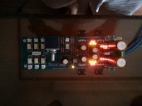
Today I complete and power-up the DCB1 but I am concerned about the offset values:
0,7mV and 2,5mV (?)
Those are the other values :
PSU: +10,28V and -9,81V
Vdrop across the 3 leds 5,551V and 5,546V
Vdrop across the 5 leds 9,662V and 9,198V
CCS resistor 2x27R - 1,739V and 1,697V
Any suggestion about the offset values?
Thanks,
Enrico
Attachments
AndrewT,
the output offset is +2,5 and -0,8
KatieandDad,
thanks for your reply... I go back in the thread looking for the offset values from the other builders... someone can reach 0,0mV so I suppose that somenthing is wrong in mine. Your answer make more confident on the results.
Regards and thanks on both of you.
Enrico
swap the jFETs that show the +2.5mVdc offset.
You need a small negative offset to indicate that the upper jFET is passing ~99% to 100% of Idss.
If the offset is positive then that indicates that the upper jFET is passing >100% of Idss. This is reputed to be not good for jFET life and not good for jFET sound quality.
You need a small negative offset to indicate that the upper jFET is passing ~99% to 100% of Idss.
If the offset is positive then that indicates that the upper jFET is passing >100% of Idss. This is reputed to be not good for jFET life and not good for jFET sound quality.
The 2 jfet are swapped.
Here the new reads...
The one that was +2.5 now is -1.6. The other one -0,6.
Thanks to everyone in the thread that make me in condition to realize this fantastic project.
I am finishing the F5TV2... I can't wait to earing the results!
Regards,
Enrico
Here the new reads...
The one that was +2.5 now is -1.6. The other one -0,6.
Thanks to everyone in the thread that make me in condition to realize this fantastic project.
I am finishing the F5TV2... I can't wait to earing the results!
Regards,
Enrico
Terry,
You could try one of these guys:
Dantimax (elektronik) - Selectors_-_attenuators,
I'm sure there are also similar products from various suppliers in Hong Kong that advertise on eBay, such as:
stereo audio channel input selector board kit ! | eBay
Best Ian
You could try one of these guys:
Dantimax (elektronik) - Selectors_-_attenuators,
I'm sure there are also similar products from various suppliers in Hong Kong that advertise on eBay, such as:
stereo audio channel input selector board kit ! | eBay
Best Ian
I have the HOT ROD version without the relay section, so I designed it myself (see link)Maybe a little off topic but does anyone make a PCB for just the relay section as used in this project. I am finishing up an X-BosoZ and am going to need a way to deal with the various inputs.
Thanks, Terry
http://www.diyaudio.com/forums/anal...otrodded-blue-dcb1-build-324.html#post3601723
Right now the PCB's are being shipped to be. Hope to receive them within two week from now. When the PCB's arrive I have to test them to make sure all is working according to plan. If you're interested you can send you a PCB. I ordered 10 of them, but in the end I only need one or two
edit: ps. The board can also be used for input selection only, so the volume pot is not absolutely necessary.
Last edited:
Yeah, too bad we don't have a "Pre-amp" forum. A PCB for just the relays that would go balanced or unbalanced, user's choice. Maybe someone who is good a PCB design could could do a single sided PCB design that we could etch. Four channels would probably be good enough for most folks.
Blessings, Terry
Blessings, Terry
Mez heatsinking advice slought for IRFP240 pair
Hi Gents, May I please ask a question?...goody
On my Mez all OK- DC offsets low enough (5mv/1mv) but on my IRFP240 (BOTH) get scarey hot! i cant touch them for more that 5 seconds (so must be about 50 degrees ish?) they are heat sinked but still get very hot (in my opinion) so could I:
a. Have one common heat sink joining both the IFRP240 together? Like a right angled piece of alimium running along lengh of the case?.
b .and/or Have a common heat sink that butts on to the lid (which is connected to mains earth via the chassis) as the lid is 3 MM thick aluminum and would be a good heat sink?
Due to lack of space i don't have the option of bolting them to the bottom of the case which would be ideal.
I understand one side draws a bit more current that the other pair of IRFP9240 (which are always cool to the touch) so are prone to get hot but I think my pair of IRFP240 get way to hot after half an hour or thereabouts...dont want any meltdowns do we?...sounds nice though..
cheers Gents
Johnny
Hi Gents, May I please ask a question?...goody
On my Mez all OK- DC offsets low enough (5mv/1mv) but on my IRFP240 (BOTH) get scarey hot! i cant touch them for more that 5 seconds (so must be about 50 degrees ish?) they are heat sinked but still get very hot (in my opinion) so could I:
a. Have one common heat sink joining both the IFRP240 together? Like a right angled piece of alimium running along lengh of the case?.
b .and/or Have a common heat sink that butts on to the lid (which is connected to mains earth via the chassis) as the lid is 3 MM thick aluminum and would be a good heat sink?
Due to lack of space i don't have the option of bolting them to the bottom of the case which would be ideal.
I understand one side draws a bit more current that the other pair of IRFP9240 (which are always cool to the touch) so are prone to get hot but I think my pair of IRFP240 get way to hot after half an hour or thereabouts...dont want any meltdowns do we
?...sounds nice though..cheers Gents
Johnny
- Home
- Amplifiers
- Pass Labs
- Mezmerize DCB1 Building Thread