Only in production replacement is Linear Systems LSK170B. The DIYA store has them in matched sets. Member myleftear recently suggested this source of unmatched & matched new old stock Toshiba 2SK170BL as genuine: Studio Electronics, INC.
Also a small stock of unmatched LSK170B right now appears at: NAC semi
All the above sources are located in the USA
So, I purchased 102 pieces of LSK170B from Linear Systems. I was able to obtain 9 quads matched to +/-0.1ma - 3 more than I was aiming for.
Thanks again!
If I use a LS2SK170B quad that measures 7.02ma, 7.06ma,7.07ma and 7.08ma, is there benefits for a particular placement for each of these? Something about "the upper one biases the lower one".
Also, have quads with a higher IDSS. Any advantage to using higher or lower quads.
Thanks!
Also, have quads with a higher IDSS. Any advantage to using higher or lower quads.
Thanks!
Those are very close to surely measure which one is slightly higher in IDSS than the other, only touching them changes it. In any case those with the connected together S & G pins in a DCB1 signal pair are the ones to pick with a slightly lower IDSS indication.
More IDSS also means more Yfs or GFS (tansconductance) which is beneficial for THD. But at that IDSS region the GFS/ID curve is already at almost a plateau i.e. not particularly gainy. Don't go over 8-9mA IDSS for dissipation reasons. 9mA at 10V across each JFET is 90mW. I wouldn't use K170 and alike over 100mW. They are 400mW at 25C devices thus at 40C or more they should be already heavily derated and better kept running on even lower mW for long term reliability. Not any different than prudently using power transistors at much lower bias Watts than their nominal continuous max when in a Class A amplifier.
More IDSS also means more Yfs or GFS (tansconductance) which is beneficial for THD. But at that IDSS region the GFS/ID curve is already at almost a plateau i.e. not particularly gainy. Don't go over 8-9mA IDSS for dissipation reasons. 9mA at 10V across each JFET is 90mW. I wouldn't use K170 and alike over 100mW. They are 400mW at 25C devices thus at 40C or more they should be already heavily derated and better kept running on even lower mW for long term reliability. Not any different than prudently using power transistors at much lower bias Watts than their nominal continuous max when in a Class A amplifier.
Thanks Salas but I'm still confused. What does 'inside the quad and not L and R mean? For each channel there are two FETS in the buffer. One is connected to V+ the other to V-. and the S and D juncton of the tow is the output of the follower, with hopefully 0V offset. So the question is, given a pair for each channel,and the pair in each channel do not match Idss exactly, is it better to place the FET with the slightly higher or lower IDss of he pair connected to V+? Or does it even matter? Thanks
Thanks Salas but I'm still confused. What does 'inside the quad and not L and R mean? For each channel there are two FETS in the buffer. One is connected to V+ the other to V-. and the S and D juncton of the tow is the output of the follower, with hopefully 0V offset. So the question is, given a pair for each channel,and the pair in each channel do not match Idss exactly, is it better to place the FET with the slightly higher or lower IDss of he pair connected to V+? Or does it even matter? Thanks
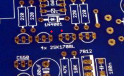
Picture the signal quad on PCB. The inner JFETs noted with red dots are for slightly less IDSS except there is a perfect match.
Their gate and source goes to -V.
Its the same like saying "better place the FET with the slightly higher IDss of the pair connected to V+" that's correct. Those outer located guys. Not of much practical importance, but that's the right way since asked.
Attachments
Salas thanks for clarifying that the lower Idss grade of the K170, 'A' and 'GR', work in the power supply section. Building a symmetrical psu B1 buffer
It looks like a TKD potentiometer is a good upgrade from the Alps, I can only find a 25K one at hificollective in UK and the motorized one is only a little more money - about ~$138 shipped. Has anyone else gone this route? Seems like once you move beyond the Alps the sky is the limit on volume controls.
It looks like a TKD potentiometer is a good upgrade from the Alps, I can only find a 25K one at hificollective in UK and the motorized one is only a little more money - about ~$138 shipped. Has anyone else gone this route? Seems like once you move beyond the Alps the sky is the limit on volume controls.
They have done it a lot in the DCG3 and they raved about the move form ALPS 20K log to TKD 25K log. Although its an ouch price difference. There is a small size affordable enough TKD also which is clearly better than the ALPS but not quite like the big TKD. The DCG3 is a more expensive build in general nonetheless and more susceptible to the pot so maybe they make the move easier there.
You are correctly stating dB. Builders many times just measure the gangs in a stereo pot for kOhm at various positions to determine matching. Not right, we should measure the attenuation in dB per gang/channel to determine how they follow each other. By using a signal source.
- Home
- Amplifiers
- Pass Labs
- Mezmerize DCB1 Building Thread

