This is my first time testing JFET's. I've tested 14 pcs.
Could someone look at my number's and see if they make since.
I'm hoping #s,1,4,6,and 14 are close enough for the signal path, and the remaining are okay for the PSU.
Thanks so much for any help.
Could someone look at my number's and see if they make since.
I'm hoping #s,1,4,6,and 14 are close enough for the signal path, and the remaining are okay for the PSU.
Thanks so much for any help.
Attachments
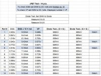
Use the lower IDSS for the CCS
In other words 7&12 for those in series with each five LEDs string
looking for alternatives
Dear Community
I'm in the process of ordering the parts, which is fun already.
But there are—of course—issues, which I'd like to come around:
I'm sticking to the Mezmerize "10 Years After" BOM and Notes (PDF) from the diyAShop, it is very helpful.
But there are a few parts I can't seem to find. I'm in Switzerland, and I suspect this is the cause of some parts not being available from mouser.
The parts in question are:
transformator (recommended alternative? how about R-Core?)
LED (What values are important—current, voltage, power?)
Fischer Side-sinks
Pot ALPS RK27 (20k... 20k is ideal I presume? Mouser offers 10k or 100k)
I know, this is out of my ignorance, but I'd be glad for advice...
Thanks many times!
david
- Any type transformer you prefer in 2x15VAC 50VA spec
- VF at 5mA 1.8V-1.9V (see datasheet I/V curve) many red or orange LED will do. Example Kingbright WP2773ND.
- You can alternative mount the MOSFETS at the chassis floor to cool. Else any sinks with comparable C/W spec to the Fischer that fit the space.
- Farnell/Newark/Element14 for the 20K Alps and the Fischer?
- 10K also works if there's no way to get the 20K. The latter can be a milder load on the source equipment.
My head is spinning regarding what pot choice to choose for my DCB1.
There’s three choices:
Khozmo Series pot, impedance 25K (steady impedance, but a ‘series’ of resistors and solder joins in the signal path).
Khozmo Shunt pot, impedence 20K (only two resistors in signal path, but variable impedence depending upon volume position).
Khozmo Ladder pot, best quality solution, but only available in 10k. Is that OK for DCB1 or too low?
My sources will be a Hugo TT2 DAC, and a WAD Phono 3 stage (still being built), and the occasional use of a cassette deck.
The DCB1 will be used at various times with a Quad 606, Quad 303, and (later this year) a Leak Stereo 20.
So I’m looking for best compatibility, and sound quality.
Which to choose?
Thanks")
There’s three choices:
Khozmo Series pot, impedance 25K (steady impedance, but a ‘series’ of resistors and solder joins in the signal path).
Khozmo Shunt pot, impedence 20K (only two resistors in signal path, but variable impedence depending upon volume position).
Khozmo Ladder pot, best quality solution, but only available in 10k. Is that OK for DCB1 or too low?
My sources will be a Hugo TT2 DAC, and a WAD Phono 3 stage (still being built), and the occasional use of a cassette deck.
The DCB1 will be used at various times with a Quad 606, Quad 303, and (later this year) a Leak Stereo 20.
So I’m looking for best compatibility, and sound quality.
Which to choose?
Thanks
Fortunately all of your amps are sensitive and can be used with phono and cassette deck as sources when the line controller adds no voltage gain.
From what I saw in a couple of quick schematic search results, the WAD phono 3 uses an ECC83 valve as last stage cathode follower through 1k output damping resistor. I wouldn't expect less than 2k output impedance from that circuit. It should perform better on classic high impedance line inputs.
Cassette decks are some times buffered inside, sometimes not. Few state what minimum load impedance is best for them, most state nothing. The usual tape monitor input impedance of preamps and integrated amps back in the day was circa 50k or higher.
Considering all the above, get a 50k series. Better safe than sorry. Up the DCB1's 220k across input resistors to 1Meg as well. Because keeping the 220k would affect a 50k pot the wrong way.
Good luck with finishing your builds and remember to tell us about your results.
Thanks. Will definitely post some pics once completed.
Hi
I bought a complete Hypnotize kit. Can’t find a build thread on that so hopefully its ok to ask here?
The shunt resistors in the kit is 4pcs 10ohm/3,75W and 2pcs 2,7ohm/3,75W. My transformer is going to be 60VA and diodes are MUR860.
I want to hotrod to 600mA which seems to be a good option (or)?!
How should I combine these resistors? Someone who made to parts kit must have had an idea. The board print suggests 10/5W.
Thanks
Hypnotize is there: Salas hotrodded blue DCB1 build
Those set resistors are probably for three scales*
Ask any further questions about it in that thread
*Single 10R, double paralleled 10R, single 2R7 for ~150-300-500mA
Those set resistors are probably for three scales*
Ask any further questions about it in that thread
*Single 10R, double paralleled 10R, single 2R7 for ~150-300-500mA
Hello guys,
I've read carefully ~100 pages of the thread and I think I should be able to carry on this project. I have some questions before I place the order:
1. Can I use a 10k series stepped attenuator in place of the pot? I already own one and I would save that ~25 bucks for an ALPS pot. Will it worsen the result?
2. Which case dimension do you suggest? Do you know an HiFi2000 reference model from the diyaudiostore?
3. For signal wiring would you suggest using separate grounds for all the inputs or a U shaped ground bus terminated in the output connector?
1. Yes. The result will be good enough still because a switcher pot
2. Others may suggest chassis types better than me
3. Separate because the Mez PCB routes the grounds
Thanks for the feedback Salas
ALMOST READY TO TEST
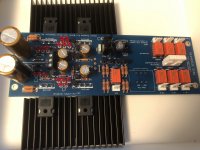
Finally I got to spend a little time putting the board together. My plan is mill away a portion of the heat sink fins so that mosfets have a nice flat surface to get rid of the heat. I am going to ask for a case for Christmas!
A couple of questions:
Is there enough height in the Dissipante 2U (with baseplate) for the B1? I measured and it seems to be adequate but like everything else, people that have gone before me know things I have not considered.
Also the 3 unmarked pads in the middle of the board - are these just used to test the power supply portion of the board - or can they be used to power other things like a relay circuit, motorized potentiometer etc. - or am I better off adding a separate power supply for those things?
Thanks for all your many contributions to this fascinating and educational experience!
Attachments
- Home
- Amplifiers
- Pass Labs
- Mezmerize DCB1 Building Thread