Hello Salas, I did solder new LED's but still no luck here. I measured BC550, it is 0.1, going to replace it for another one (have to order) then checked the mosfet and not getting the 3.5 to 4 v here , but I already changed this when I replaced the LED's, don't know but this mosfet are kind of delicate.
The K170 JFETs should show few decades of Ohm between their outer pins. Can be measured when already on PCB in this circuit. Do that check also. Maybe one is open or shorted.
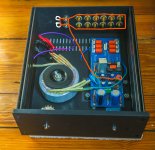
Hello Salas, I did some test today, measured the mosfet , it was reading 0.00v , then put a new one there and change some LED's and now is working. The strange thing was that I changed that mosfet before but did not worked, glad that I got a new DMM that lite the LEAD's. I have two LED's that lit very dim, do I have to change them or leave them like that?(you can see them in the picture). Tomorrow going to check voltages to see how is working. Thanks in Advance.
Attachments
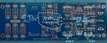
Hello Salas, I did some test tonight:
1- V+ =9.97v
V- =- 9.26
2- Voltages across R1 resistors : 1.56v and -1.43v
Offset voltages, I'm not sure about this, I put multimeter to read dcv (600m) and got
-0.00mv and 0.3mv
Do I have to test another points on the board?
Thanks
1- V+ =9.97v
V- =- 9.26
2- Voltages across R1 resistors : 1.56v and -1.43v
Offset voltages, I'm not sure about this, I put multimeter to read dcv (600m) and got
-0.00mv and 0.3mv
Do I have to test another points on the board?
Thanks
Thanks Salas for your response. I have some questions:
1-) The correct way to connect the RCA's is one insulator to outside chassis the other one inside chassis with the lug touching the chassis or lug on top of that insulator ??
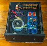
2-) the picture show how I'm connecting inputs returns with a solid cooper wire through all the inputs plus 2 outputs (adding another one for a sub) and then returning to the output pin on PCB. Is this correct ? Also how to connect the 2 outputs ? Do they need a resistor between them ?
3-) Since I'm using a 2 pole 6 way Elna switch selector for all the inputs, can I use the other pole to lite the inputs, if yes, how can I do it the easy way.
Thanks in advance.
Rommel lagrange
1-) The correct way to connect the RCA's is one insulator to outside chassis the other one inside chassis with the lug touching the chassis or lug on top of that insulator ??
2-) the picture show how I'm connecting inputs returns with a solid cooper wire through all the inputs plus 2 outputs (adding another one for a sub) and then returning to the output pin on PCB. Is this correct ? Also how to connect the 2 outputs ? Do they need a resistor between them ?
3-) Since I'm using a 2 pole 6 way Elna switch selector for all the inputs, can I use the other pole to lite the inputs, if yes, how can I do it the easy way.
Thanks in advance.
Rommel lagrange
Attachments
Thanks Salas for your response. I have some questions:
1-) The correct way to connect the RCA's is one insulator to outside chassis the other one inside chassis with the lug touching the chassis or lug on top of that insulator ??
2-) the picture show how I'm connecting inputs returns with a solid cooper wire through all the inputs plus 2 outputs (adding another one for a sub) and then returning to the output pin on PCB. Is this correct ? Also how to connect the 2 outputs ? Do they need a resistor between them ?
3-) Since I'm using a 2 pole 6 way Elna switch selector for all the inputs, can I use the other pole to lite the inputs, if yes, how can I do it the easy way.
Thanks in advance.
Rommel lagrange
1. Lug on top of insulator
2. Yes its a working alternative method than running three wires per RCA pair to the board. DON'T create a ground loop i.e. don't close both ends. It should be a U. To connect two outputs better use 100R between the main and secondary one in series with signal hot.
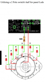
3. See the attached crop from my Select standalone board's guide. Steal 12V DC after the Mez's reg chip for that job. 10K is for 1mA which lights up a panel LED potently but not too irritatingly to the eye especially at night. Want more light? Lessen the resistor's value.
Attachments
1. Lug on top of insulator
2. Yes its a working alternative method than running three wires per RCA pair to the board. DON'T create a ground loop i.e. don't close both ends. It should be a U. To connect two outputs better use 100R between the main and secondary one in series with signal hot.
3. See the attached crop from my Select standalone board's guide. Steal 12V DC after the Mez's reg chip for that job. 10K is for 1mA which lights up a panel LED potently but not too irritatingly to the eye especially at night. Want more light? Lessen the resistor's value.
Can I use blue LED's ? 0.25w resistor is fine? Sorry too many stupid questions, but I in the process of mod the chassis and wiring the pot and switch.
Thank you , I'll do that. You see the gray RCA, is a Cardas and it does not have a lug and I was trying to solder the cooper wire to the body of the cardas but did not solder to it. Do you see any problem if I left it like that?
There will be no ground return for it if you leave its ground plate unsoldered like that. It has dents that you could saturate with solder and attach the copper ground buss wire.
Can I use blue LED's ? 0.25w resistor is fine? Sorry too many stupid questions, but I in the process of mod the chassis and wiring the pot and switch.
Yes, whatever color you like. They are not part of the main circuit to have self noise considerations anyway (blue and white are noisier when used as Vref). They may have circa 3.5V forward voltage drop the blue ones and are generally brighter than red so use the same 10K for little less current cutting some more brightness. 0.25W in this case is super reliable, just few mW are on it (12-3.5=8.5V/10k=0.85mA*8.5V=7.225mW).
What is funny, after expending hours and hours modding the chassis wiring the inputs, the pot and switch ( let me tell you magnet wire is not fun to work with ) then almost 2:00 am I was ready for the first time in almost 6 years to fire up and have a listening, plug the Mezmerize and nothing happened, zero, nada no lights. I was shock then I realized the Mezmerize has a power switch, turned on, still nothing, zero, nada. Came to my mind, maybe the power inlet filter did not come with the fuses. Did take the cartridge out and Boooom no fuses. Now I have to wait till Tuesday to have a listening. Shame on me.
Last edited:
- Home
- Amplifiers
- Pass Labs
- Mezmerize DCB1 Building Thread