Hello all,
Just picked up a Threshold 400A amp. Would like some input on restoration.
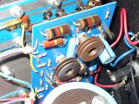
1) Will definately replace all the caps. A question arises about the resistors. Should they be replaced as well?
2) Looking for advice on the output transistors? Do they really need to be replaced? I didn't think they wear out.
3) Bias setup: Does anyone have a good procedure to perform?
4) Any idea where I can get a power switch or handles? The unit looks good for it's age, but the handles are missing.
Thanks in advance!
Just picked up a Threshold 400A amp. Would like some input on restoration.
1) Will definately replace all the caps. A question arises about the resistors. Should they be replaced as well?
2) Looking for advice on the output transistors? Do they really need to be replaced? I didn't think they wear out.
3) Bias setup: Does anyone have a good procedure to perform?
4) Any idea where I can get a power switch or handles? The unit looks good for it's age, but the handles are missing.
Thanks in advance!
![!B1k-cWQEGk~$(KGrHqV,!iUE)q1UfjL0BMfBI(GN)Q~~_3[1].jpg](/community/data/attachments/187/187696-3ddd0dd74c3f68b8f84d7c4f680feaa7.jpg)
![!B1k-djQBGk~$(KGrHqJ,!jQE)pwU,lNVBMfBI,g6Rw~~_3[1].jpg](/community/data/attachments/187/187700-4d15e58cf2d4229b54b14165a85ad00f.jpg)
Hello all,
Just picked up a Threshold 400A amp. Would like some input on restoration.
1) Will definately replace all the caps. A question arises about the resistors. Should they be replaced as well?
2) Looking for advice on the output transistors? Do they really need to be replaced? I didn't think they wear out.
3) Bias setup: Does anyone have a good procedure to perform?
4) Any idea where I can get a power switch or handles? The unit looks good for it's age, but the handles are missing.
Thanks in advance!
1. no need for resistors ; in any case - re-flow all suspicious solder joints
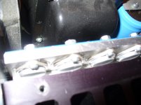
2.if amp is working OK - there is no need ; inspect carefully condition of white thermal goo around outputs ; if needed - you must renew that ; dismantle ( one by one ) every output , clean transistor, mica , heatsink and grease again
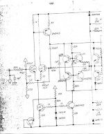
3. search in forum - it's published several times ; I'll attach that again , but I don't have it in tis comp
4. someone will chip in ....... I dunno
1. no need for resistors ; in any case - re-flow all suspicious solder joints
2.if amp is working OK - there is no need ; inspect carefully condition of white thermal goo around outputs ; if needed - you must renew that ; dismantle ( one by one ) every output , clean transistor, mica , heatsink and grease again
3. search in forum - it's published several times ; I'll attach that again , but I don't have it in tis comp
4. someone will chip in ....... I dunno
Thanks!
I did search the forums, and I did find one that looks promising, BUT, it's missing the first three steps.
IF one decides to replace the output devices, do you use the same, or look for a sub? I wonder if a sub would change the character/behaivor of the amp?
Thanks!
........
IF one decides to replace the output devices, do you use the same, or look for a sub? I wonder if a sub would change the character/behaivor of the amp?
why to replace them , if they are functional ?
Attachments
why to replace them , if they are functional ?
An excellent question! I was initially thinking that as well. However, I've been advised by former Threshold techs that the old aluminum cans have been overly stressed over time, and could easily fail. My buddy (who's also a outstanding tech), thinks cleaning up the mounting of the existing devices should be performed instead. He told me he has good individual pads for them.
Thanks so much for the data. It looks like the same stuff I found here on DIY (Pretty sure you posted it before, much thanks!)
If you look at the bias procedure, it starts on step 4, so I don't know what the first three steps were. Do you remember what they were?
I will not loose a sleep regarding new outputs ; and that after more than 20 years of service work

I don't have that - missing - page , but I think that you have more than enough information later in document
I will not loose a sleep regarding new outputs ; and that after more than 20 years of service work
I don't have that - missing - page , but I think that you have more than enough information later in document
That was my thought as well. It sounds outstanding as is right now!

I reckon you are right. Should be able to work out the bias procedure with what you provided. Again, much thanks!
Well, the most recent email I received from the Threshold repair guru strongly suggested that the output devices be replaced.
Given that advice, was lookig at replacing the old devices with the following:
ON MJ21193/MJ21194
If I read other threads correctly on DIY, this should be a drop im for the 400A, and provide better max voltage/current performance.
Anybody actually used these on a 400A? If so, how did it work out?
Given that advice, was lookig at replacing the old devices with the following:
ON MJ21193/MJ21194
If I read other threads correctly on DIY, this should be a drop im for the 400A, and provide better max voltage/current performance.
Anybody actually used these on a 400A? If so, how did it work out?
OK
if Guru sez , then you must obey
if I can recollect my memory - there was a thread started few years ago by one bitchy guy , and I just couldn't understand how and why boyz (including Papa ) gave him so much help and information for his T. repair
I think that there you'll find some more info about best outputs
but - if Guru already give you advice - listen to him
when you don't have experience ( in exact matter) of your own - you must trust someone .
OK
if Guru sez , then you must obey
if I can recollect my memory - there was a thread started few years ago by one bitchy guy , and I just couldn't understand how and why boyz (including Papa ) gave him so much help and information for his T. repair
I think that there you'll find some more info about best outputs
but - if Guru already give you advice - listen to him
when you don't have experience ( in exact matter) of your own - you must trust someone .
Zen, since it was the guru (Jon S.) who advised me on this, as you said, must trust someone. Since I really enjoy the sound from this amp, want to make sure it's done right.
I found that thread you mentioned, and yes, much heartache. I found another thread where Papa suggested these devices (which I think are the smae ones Threshold used for their amps in the 80s and early 90s).

Well, it's taken a LOT longer to finish this, but almost there.
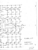
Ran into a slight problem: While working on the driver board, accidentally cracked a diode. The board I've got looks slightly different from the schematics listed here on the site.
The cracked diode has a part number of 1N75A, which appears to be a old germanium type. Was wondering if a 1N4148 would work in place of the original. If so, will replace all of the diodes.
- Status
- This old topic is closed. If you want to reopen this topic, contact a moderator using the "Report Post" button.
- Home
- Amplifiers
- Pass Labs
- Threshold 400A Looking for advice on restoration