Sorry for the delay, but I decided to build my own test jig to get a better picture of the noise spectrum.
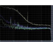
There are two plots here. I had to go to a double shielded enclosure with the outside shield connected back to signal ground on my A/D. There was still some slight mains hum depending on where I put the box on my bench (out in the middle of the room was best). In any case it was reduced to 2nV or so. I tracked it down to the input cap. I thought I connected the outside foil to ground, but it seems the end termination and FET lead is enough. Next rev will have extra care here. The 997Hz tone is a mystery. I thought it might be the cal oscillator on my scope but it wasn’t.
The noise is plotted on a log scale with -87.2 dB = 1nV/rt-Hz. This was established by taking the best FET and adding a reference resistor in the gate, a Vishay 10k .001% oil immersed precision resistor. I then scaled the plot down to 1nV. This theoretically even corrects the measurements for temperature but this is not necessary under normal lab conditions. I like this better than inserting a tone especially when using FFT’s, everything is scaled without the tedium of keeping track of bin equivalent noise BW.
All the FET’s were measured at 1.2mA Id. The lowest plot is my reference line. It varies just a little and I took an estimate around 1kHz of -87.2 dB. The next two plots (moving up) are a 2SK372 (Idss = 24.19mA) and 2SK369 (Idss = 14.75) respectively. Note the scale, we are only looking at .5nV – 3nV or so. The last plot is a random 2SK170. This is a very nice example of GR noise that would not show up well on a Quantech since it is only 3nV at 10Hz. These noise levels should scale as the fourth root of Id (one of the things that I want to do eventually).
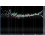
The second plot is all three FET’s with Rg = 10k. It looks like the slight rise at the low end on the 2SK170 is due to the GR noise. The roll off at the high end is probably the A/D. The unexpected result is that the other two plots rise at the high end. This could be induced gate noise but probably not impact ionization since we are at low Vgs. The lack of this in the 2SK170 and the fact that the 2SK372 is in a very small package leads me to believe this is a new/different process, this defiantly needs more study. For now these two FET’s look great for MC for sure.
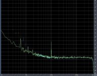
The last plot is the BF862, pretty impressive for an RF FET!
There are two plots here. I had to go to a double shielded enclosure with the outside shield connected back to signal ground on my A/D. There was still some slight mains hum depending on where I put the box on my bench (out in the middle of the room was best). In any case it was reduced to 2nV or so. I tracked it down to the input cap. I thought I connected the outside foil to ground, but it seems the end termination and FET lead is enough. Next rev will have extra care here. The 997Hz tone is a mystery. I thought it might be the cal oscillator on my scope but it wasn’t.
The noise is plotted on a log scale with -87.2 dB = 1nV/rt-Hz. This was established by taking the best FET and adding a reference resistor in the gate, a Vishay 10k .001% oil immersed precision resistor. I then scaled the plot down to 1nV. This theoretically even corrects the measurements for temperature but this is not necessary under normal lab conditions. I like this better than inserting a tone especially when using FFT’s, everything is scaled without the tedium of keeping track of bin equivalent noise BW.
All the FET’s were measured at 1.2mA Id. The lowest plot is my reference line. It varies just a little and I took an estimate around 1kHz of -87.2 dB. The next two plots (moving up) are a 2SK372 (Idss = 24.19mA) and 2SK369 (Idss = 14.75) respectively. Note the scale, we are only looking at .5nV – 3nV or so. The last plot is a random 2SK170. This is a very nice example of GR noise that would not show up well on a Quantech since it is only 3nV at 10Hz. These noise levels should scale as the fourth root of Id (one of the things that I want to do eventually).
The second plot is all three FET’s with Rg = 10k. It looks like the slight rise at the low end on the 2SK170 is due to the GR noise. The roll off at the high end is probably the A/D. The unexpected result is that the other two plots rise at the high end. This could be induced gate noise but probably not impact ionization since we are at low Vgs. The lack of this in the 2SK170 and the fact that the 2SK372 is in a very small package leads me to believe this is a new/different process, this defiantly needs more study. For now these two FET’s look great for MC for sure.
The last plot is the BF862, pretty impressive for an RF FET!
Attachments
Hello Scott,
Thousand thanks.
I almost thought you had forgotten in tons of other work that you had.
And very interesting result indeed. I never expected that 2SK372 to be so good, indeed better than the two. And BF862 is really impressive.
If you are willing, I can send you some more FETs -- 2SK366, 2SJ107, 2SK163, 2SJ44, 2SK2223, .... The trouble is that these were bought as matched pairs at a premium price, so I definitely would like to have them back this time.
At long last we have some results from one very reliable source for direct comparison. 😉
Would you care to explain your test setup a bit more, to see if it can be duplicated with reasonable effort ?
Best regards,
Patrick
PS You may of course email me if you prefer.
Last edited:
The 997Hz tone is a mystery. I thought it might be the cal oscillator on my scope but it wasn’t.
Coulda been your grand mum's hearing aid oscillating in the other room. 🙂 Or someone left the Krohn Hite 4400A on.
Wonderful work, thanks! We have no low noise environment in NJ, what with Snooki all over the telly.
For those using the current-sourced JFET source follower (alias B1) for preamp or buffer for Sallen Key filters, the 2SK372 is IMHO a much better choice. It has twice the transconductance of the 2SK370/170, with about double the capacitance. The output impedance in that circuit is thus halved. And now we know it also has quite a bit less noise.
You can easily get them (V grade) at ampslab, amongst others, at reasonable price. The V grade with +/-9V supply will run hot, so a heatsink is recommeded. (Pictures next week, as I am not in town till 15 October.)
Patrick
You can easily get them (V grade) at ampslab, amongst others, at reasonable price. The V grade with +/-9V supply will run hot, so a heatsink is recommeded. (Pictures next week, as I am not in town till 15 October.)
Patrick
Last edited:
will continue from HERE. Datasheets for 2SK372 and 2SK363 shows this is the same part but different housing.
Yes, they are very good for source follower configurations (biased with CCS), kind of punchier sound 🙂
@scott
thank you for those measurements. Great work
Yes, they are very good for source follower configurations (biased with CCS), kind of punchier sound 🙂
@scott
thank you for those measurements. Great work
Last edited:

Datasheet also suggest that 2SK170 & 2SK370 to be the same part, except that they are most likely the same specification but manufactured with different processes, with the 2SK370 probably having a smaller die, and certainly a smaller package, to save costs.
The smaller package has a dissipation disadvantage when used free air standing. It has however a big advantage when glued together on the flat face as a matched pair. The physical distance between the two silicon dies are much smaller, with about half the plastic in between. This allows much better thermal coupling between the two, and hence DC tracking. Also, if you now enclose the two with an aluminium heatsink with a cut-out of the right size and shape, you also conduct the heat from the silicon die to the aluminium much better than the standard TO92 housing.
Of course you can argue standard TO92 will do fine. But if you want to run say 15V 25mA through the device, it is very close to its rated maximum. I personally would never want to run my devices more than 25% of rated maximum, for reliability reasons.
I shall open a new thread new week to show you what I meant.
We should keep this thread for JFET noise measurement discussions only.
Patrick
Last edited:
... 2SK372 is IMHO a much better choice. ...
The only problem i see is Pd_max=200mW at 25 C (150mW at 50C).
Heatsinking, as you said, might be mandatory.
You can always use 2SK372BL, if you could get them of course. 😉
Transconductance still 2x that of 2SK170BL.
Patrick
Transconductance still 2x that of 2SK170BL.
Patrick
Look at the data above carefully.
BF862 is not quite up to it in comparison.
And it is even more difficult to get rid of the heat.
Patrick
BF862 is not quite up to it in comparison.
And it is even more difficult to get rid of the heat.
Patrick
Patrick, you are right about noise - if you want to chase the last nV of it.
Thermally, i find BF862 very easy to handle - gate pin collects the heat and it is always soldered to copper surface that takes the heat away. My prefered range of use is at 100-130mW (10V x 10-13mA) so it's an easy task . Taking into account the availability/price/performance ratio, I personally find BF862 unbeatable.
Of course, I support your efforts and I'm thankfull to Mr. Wurcer for valuable measurements.
The Idss of BF862 is 10-25mA.
Depending on batch, very few of them falls below 14mA, unless you use source degeneration, which adds noise.
If you look at the datasheet in detail, the thermal resistance quoted by the datasheet are based on PCB copper area which is not realistic. So you need to do something else to get the heat out.
Don't get me wrong. I also use BF862 a lot, and I do get the heat out. You only need to look at the B1 Turbo thread.
http://www.diyaudio.com/forums/pass-labs/140488-b1-turbo-chip.html
But for most, the 2SK372 is a very easy device to use, and is widely available.
Patrick
Juma,
considering what I said comparing the f862 to k170, it seems there is no contest with respect to noise. The k170 is noisier.
considering what I said comparing the f862 to k170, it seems there is no contest with respect to noise. The k170 is noisier.
Datasheet says so - I bought a batch of 500 and about 95% of them are with Idss in range from 12 to 14 mA.The Idss of BF862 is 10-25mA. ...
You saw my small adapter PCB for BF862 - with Pd=150mW temperature on the JFET's surface is 18 degrees C above ambient. I consider that quite good....If you look at the datasheet in detail, the thermal resistance quoted by the datasheet are based on PCB copper area which is not realistic. So you need to do something else to get the heat out. ...
True. We are also aware of some nice MC preamps designed with k170 that produce no noise that can be heard even on highly sensitive speakers. Well, k170 is certainly good enough, but BF862 and k372 are better....The k170 is noisier.
> I bought a batch of 500 and about 95% of them are with Idss in range from 12 to 14 mA.
Then you are lucky.
I had a batch of 500 which was 80% > 18mA.
At least we all agree 2SK372 is better. 😉
Patrick
Then you are lucky.
I had a batch of 500 which was 80% > 18mA.
At least we all agree 2SK372 is better. 😉
Patrick
Some more details of the measurement circuit :
http://www.diyaudio.com/forums/soli...1000-low-noise-measurement-amp-ikoflexor.html
Patrick
http://www.diyaudio.com/forums/soli...1000-low-noise-measurement-amp-ikoflexor.html
Patrick
But for most, the 2SK372 is a very easy device to use, and is widely available.
Patrick
Any place you know of that sells them at prices similar to the BF862?
As promised :
http://www.diyaudio.com/forums/soli...mance-source-follower-module.html#post2336629
Patrick
http://www.diyaudio.com/forums/soli...mance-source-follower-module.html#post2336629
Patrick
- Home
- Amplifiers
- Pass Labs
- More FET noise measurements (for EUVL)