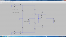
You missed 10K/4n7 on output , they are the load too!
4n7 makes a LP filter together with drain resistors (1k). 10k is not functional part of the circuit. It just represents the possible Zin of the next stage.
Well the Zen IV could also be classified as an opamp. I was referring to IC opamps.
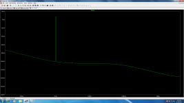
I have done simulations if you are interested
see here
http://www.diyaudio.com/forums/pass-labs/173291-zen-i-v-converter.html
I have done simulations if you are interested
see here
http://www.diyaudio.com/forums/pass-labs/173291-zen-i-v-converter.html
How about using 0.1uF instead of bulky 10uF? It's possible if the ZEN I/V is loaded by B1 running at approx. +/-10V (it's easy to scale down from +/-30V). Additional benefit is higher drive capability.
That is a quite good idea, juma!
I have a hypno board left (wise idea to buy some more).
How shall I do the down scaling? Just change the resistors for the same current as with 30V?
Greetings
Sam
RC combo is the easiest way to do it (like R1/C1 or R2/C2 in ZEN I/V schematic). For example:...How shall I do the down scaling? ...
I make my buffers with BF862 running at 10mA. We want to loose 20V. So, we'll need 2k resistors rated at 0.5W at least. C member can be usual 220uF or less.
R2 sets the DC offset, buffer's Zout is approx. 50R. Schematic would look like this:
Attachments
Last edited:
I do not understand why extra DACs would be needed (did you mean 2 total, or 2 extra? 3?).Problem with this is you would be stuck with balanced ouput and the input would require 2 extra DACs. R2R DAC chips aren't chip or easy to find these days.
Current-output DAC chips often have two outputs; each is a complement of the other. When the sample bits are loaded for conversion, each bit switches a fixed current to one or the other output, and thus the total current through the chip remains constant - and that's much better than having the total current load on the supply change frequently.
In other words, with a complementary current-output DAC, only one chip is needed.
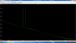
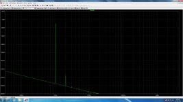
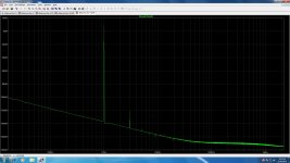
Thanks for the info, thanh1973. As I can see on your balanced model (the corrected version of THD), there is only about -130 dB (+10dB fundamental and -120 dB of 3rd harmonic), this data doesn't correspond to Mr. Pass's THD graph - the best result is at about 0.5V output with 0.0026% THD, while -130 dB is about 0.00003% THD.
AFAIK AP should not be a cause of such difference (x87).
Concerning the op amps - what is the difference between the discrete op amp and IC op amp, if the last one has been designed correctly?
AFAIK AP should not be a cause of such difference (x87).
Concerning the op amps - what is the difference between the discrete op amp and IC op amp, if the last one has been designed correctly?
Last edited:
Hihihi
I could have used my brain...
I do not understand why extra DACs would be needed (did you mean 2 total, or 2 extra? 3?).
Current-output DAC chips often have two outputs; each is a complement of the other. When the sample bits are loaded for conversion, each bit switches a fixed current to one or the other output, and thus the total current through the chip remains constant - and that's much better than having the total current load on the supply change frequently.
In other words, with a complementary current-output DAC, only one chip is needed.
You are talking about Sigma-Delta technology, surely one would build this new I/V with a proper R2R chip.
The guy with the spice model, can you tell us the DC across each of the coupling caps?
You are talking about Sigma-Delta technology, surely one would build this new I/V with a proper R2R chip.
The guy with the spice model, can you tell us the DC across each of the coupling caps?
It remains the dilemma ... with the R2R chip if going NOS or not ...
Thanks Nelson! 
The part which I liked most is: "Interestingly, it took a long time before anyone seemed to understand what was going on. I showed it to a “designer” at a major DAC manufacturer at the time and he told me that he didn't see how it could possibly work, and he wasn't the only one."
I just wonder how many nice inventions ended up in a drawer because somebody "up there" couldn't understand how it works, or refused to admit that it can work. Now, what can be a better joy than proving them wrong!")
The part which I liked most is: "Interestingly, it took a long time before anyone seemed to understand what was going on. I showed it to a “designer” at a major DAC manufacturer at the time and he told me that he didn't see how it could possibly work, and he wasn't the only one."
I just wonder how many nice inventions ended up in a drawer because somebody "up there" couldn't understand how it works, or refused to admit that it can work. Now, what can be a better joy than proving them wrong!
It remains the dilemma ... with the R2R chip if going NOS or not ...
I'm adding this to a PMD100 oversampling AD1862 DAC I have been working on. Not a fan of NOS.
I'm adding this to a PMD100 oversampling AD1862 DAC I have been working on. Not a fan of NOS.
I do not go crazy for NOS aswell , I have AD 1865 with an old digital filter ... will try it .
PS. : is it the PMD100 difficult to find ? Do you have one to sell me ?
Thanks
Last edited:
R2R DACs the likes of AD1865 has low output current, say 1~2mA. So using 1k drain resistors is not going to give enough gain. Which means you need to go to something like 2.4k or 4.7k. The would need power resistors, like 2W.
The consequence of that is that the rail has to go up (by another 14v and 37V respectively). The output impedance now becomes 1.2k and 2.35k (high-ish but solvable with a buffer)). But the input impedance of the JFETs go up further due to Miller effect. If you use oversampling, then you might want higher bandwidth, and this does not help.
I did not suggest folded cascode for no reasons. If you have gone through the same design process, you would realise the limitations. Still, you can knock one together within an hour, and it probably would sound very nice if you use a sigma-delta DAC with 5mA output.
Patrick
R2R DACs the likes of AD1865 has low output current, say 1~2mA. So using 1k drain resistors is not going to give enough gain. Which means you need to go to something like 2.4k or 4.7k. The would need power resistors, like 2W.
The consequence of that is that the rail has to go up (by another 14v and 37V respectively). The output impedance now becomes 1.2k and 2.35k (high-ish but solvable with a buffer)). But the input impedance of the JFETs go up further due to Miller effect. If you use oversampling, then you might want higher bandwidth, and this does not help.
I did not suggest folded cascode for no reasons. If you have gone through the same design process, you would realise the limitations. Still, you can knock one together within an hour, and it probably would sound very nice if you use a sigma-delta DAC with 5mA output.
Patrick
Ok , I had nice experience with a Sony sigma delta current output dac , but do not have it anymore . Could you suggest a nice sigma delta dac for purchase , spidf or usb ?
Thanks
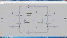
quick & dirty
Patrick,
TY, great inspiration for my Assemblage DAC3.
(continue at this rate and i'll have to rename it to EUVL DAC)
Last edited:
> continue at this rate and i'll have to rename it to EUVL DAC
a) It is an IV and not DAC.
b) It comes from Mr Curl and not me.
c) I am already into version 4 of this, and the one published is version 0.
And no, I do not publish work in progress. Sorry guys.
But Version 0 sounds real nice. Just too much current.
Patrick
PS I do not use sigma delta DACs, but Sabre is one, though you need to have high bandwidth IV to match.
- Home
- Amplifiers
- Pass Labs
- Zen I/V Converter