Hello All,
Iv'e been considering the addition of a balanced to SE conversion circuit for the balanced Zen IV used with my Sabre DAC. There have also been one or two other request in this thread. Something discrete is a must for me at this point.
I have looked and done some simulation work on discrete opamps like those from Nelson's article, Borbely, and others. To achieve measureable performance that would complement the Sabre and ZenIV, they became too complex for what I wanted to achieve. In the end, I came up with something I really like.
The good news is that you can also add some gain and the low pass filter in this stage and keep any fully differential ZenIV well within the Zen Zone (my opinion there).
More details about the stage itself are here.
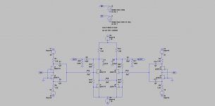
Here is a balanced ZenIV with the new stage. This one has some gain to bring a lower level IV solution up to normal voltage levels if needed. To use it as SE, connect to the out+ and ground. Balanced outs are included as well.
If anyone spots a problem, constructive feedback is appreciated.

Dave
Iv'e been considering the addition of a balanced to SE conversion circuit for the balanced Zen IV used with my Sabre DAC. There have also been one or two other request in this thread. Something discrete is a must for me at this point.
I have looked and done some simulation work on discrete opamps like those from Nelson's article, Borbely, and others. To achieve measureable performance that would complement the Sabre and ZenIV, they became too complex for what I wanted to achieve. In the end, I came up with something I really like.
The good news is that you can also add some gain and the low pass filter in this stage and keep any fully differential ZenIV well within the Zen Zone (my opinion there).
More details about the stage itself are here.
Here is a balanced ZenIV with the new stage. This one has some gain to bring a lower level IV solution up to normal voltage levels if needed. To use it as SE, connect to the out+ and ground. Balanced outs are included as well.
If anyone spots a problem, constructive feedback is appreciated.
Dave
Attachments
Apologies regal. I changed the subject with a new post before seeing yours.
I like the idea. Would it be possible to do it with cascoded JFETs instead of MOSFETS. Any other ideas how to get the distortion down into the range of the original?
Dave
If I remember right it was Evils idea, I posted the spice file so the group could try other means to get the distortion down.
Thanks! Balanced is important to me for any new audio equipment acquisitions, whether I build or buy. Of course, the realities are that it still be necessary to interface with unbalanced.Here is a balanced ZenIV with the new stage. This one has some gain to bring a lower level IV solution up to normal voltage levels if needed. To use it as SE, connect to the out+ and ground. Balanced outs are included as well.
PCM1704 + Zen IV + Transformer done
Happy to report that the sound is VERY VERY vivid and sweet.
Zen IV seems more "romantic" than original D1.")
(But I didn't use LL1674 for D1 output stage)
PCM1704 Parallel + BG NX + LL1674 give me 5.1Vrms balance output. Fairly enough. Sound is so sweet, a little bit lack details but still enough.
Viva Zen IV...
Happy to report that the sound is VERY VERY vivid and sweet.
Zen IV seems more "romantic" than original D1.
(But I didn't use LL1674 for D1 output stage)
PCM1704 Parallel + BG NX + LL1674 give me 5.1Vrms balance output. Fairly enough. Sound is so sweet, a little bit lack details but still enough.
Viva Zen IV...
This is a quick & dirty schematics just to show the idea of a cascoded complementary JFET IV.
I hesistated to call it cascoded Zen IV, as it is more of a "Blowtorch IV".
No coupling output caps, but consumes quick a bit more current.
Patrick
Hi Patrick
I like no coupling caps but wouldn't be required trimmer to null DC
In practice
there are missing some resistor values and can I use Irf610/9610 Instead off original MOSFETS
Please search the original Blowtorch thread for more circuit details.
It is just an idea, has not been proven. So build at own risk.
Patrick
Hi, I quick built a test circuit. It works fine... the only problem is
DC drifting of output terminal. No matter how I trim the resistor to
fine tune the output MOSFET Gate, the output DC is always drifting from
+0.2V ~ 0.3V (seems co-related to temperature..)
Is this normal?
Thanks,
a) You need to thermally couple all the devices. So mount all the MOSFETs on a piece of aluminium say 8~10mm thick, something like this :
http://www.diyaudio.com/forums/pass-labs/121228-f5-power-amplifier-24.html#post1538832
You should ideally also thermally couple ALL 4 jfets, using something like our DJFET heatsink :
http://www.diyaudio.com/forums/group-buys/135359-toshiba-dual-jfet-heatsink-6.html#post2366641
We did not design them just for fashion !!
My guess is that you will get up to a factor of 10 reduction in DC drift with thermal coupling alone.
b) The blowtorch does use a servo. Pls check out the original blowtorch thread.
Even if you were to use a servo, I would still recommend thermal coupling, to minimise the task of the servo and hence any intrusion on SQ.
A heatsink also increases the thermal time constant, and hence you can use a slower servo.
Patrick
.
Last edited:
Hi, I quick built a test circuit. It works fine... the only problem is
DC drifting of output terminal. No matter how I trim the resistor to
fine tune the output MOSFET Gate, the output DC is always drifting from
+0.2V ~ 0.3V (seems co-related to temperature..)
Is this normal?
Thanks,
would you please give us more details
schematic, values, type MOSFETS
what Is your DAC chip, do you have 0V dc at Input
Current Status:would you please give us more details
schematic, values, type MOSFETS
what Is your DAC chip, do you have 0V dc at Input
Schematics and values is about the same like previous posted.
MOSFET is J76/K213.
DAC is PCM1704 parallel per channel per phase. And it's 0V dc at input.
Output can trim to 0V for a while, but even with thermal heat sink,
there are some 80mV range drifting... increase gate cap value to 220uF
seems help little.
Also, spent quite some time to find a DC servo for the output (in BT thread)
and somewhere else, didn't find a good one. (it's a long long thread... ha ha)
use Index of / to find out
what are values of other resistors except R2, R3 - which Is said to be 200 Ohm - R5, R1, R18, R17
can we use one side of the schematic - SE output
what are values of other resistors except R2, R3 - which Is said to be 200 Ohm - R5, R1, R18, R17
can we use one side of the schematic - SE output
zen i/v for 1794
I have been vigorously looking entire diyaudio forum for any information on build of Zen I/V or D1 for PCM 1794. I have RAKK DAC board and would like to try D1 or Zen I/V. But the above is only suggestion that I could find.
I have plenty of exprience in soldering circuits, but lack knowledge to design my own variation of zen i/v or comming up with circuits neccessary to fullfill what has been suggested above.
Could any one post something if successfully built one for 1794?
If not, it'd be great if some knowledgible members could give some specific ideas/instruction to achive this. Or how exactly the zen i/v circuit would look like to add CCS and parallering BL grade JFET? ( It appears that I can get matched BL grade fairly easily in this site, but not V grade).
Thanks!
I think the best solution is to add a ccs to compensate for the current offset and let the output stage deal with the AC current variations.
However +/- 3.9mA is probably to much to handle with a low distorsion for a stage limited by the idss of the fets to around 10mA idle current (BL grade).
You can go a bit higher by paralleling and using higher grade (V, hard to find).
I have been vigorously looking entire diyaudio forum for any information on build of Zen I/V or D1 for PCM 1794. I have RAKK DAC board and would like to try D1 or Zen I/V. But the above is only suggestion that I could find.
I have plenty of exprience in soldering circuits, but lack knowledge to design my own variation of zen i/v or comming up with circuits neccessary to fullfill what has been suggested above.
Could any one post something if successfully built one for 1794?
If not, it'd be great if some knowledgible members could give some specific ideas/instruction to achive this. Or how exactly the zen i/v circuit would look like to add CCS and parallering BL grade JFET? ( It appears that I can get matched BL grade fairly easily in this site, but not V grade).
Thanks!
I have been vigorously looking entire diyaudio forum for any information on build of Zen I/V or D1 for PCM 1794.
I think that would be an interesting circuit. If I read the
datasheet correctly, the output is biased at about -6mA
centerpoint and would like to see a low impedance load.
This suggests that a single-ended Common-Gate device
could be biased through the DAC directly given an
appropriate Gate bias voltage.
I have been vigorously looking entire diyaudio forum for any information on build of Zen I/V or D1 for PCM 1794. I have RAKK DAC board and would like to try D1 or Zen I/V. But the above is only suggestion that I could find.
I have plenty of exprience in soldering circuits, but lack knowledge to design my own variation of zen i/v or comming up with circuits neccessary to fullfill what has been suggested above.
Could any one post something if successfully built one for 1794?
If not, it'd be great if some knowledgible members could give some specific ideas/instruction to achive this. Or how exactly the zen i/v circuit would look like to add CCS and parallering BL grade JFET? ( It appears that I can get matched BL grade fairly easily in this site, but not V grade).
Thanks!
Hi, as NP said, you can use D1 (Common Gate SE) similar circuit to do it.
But need to increase the bias current more than 10ma... Also, reduce the drain resistor value because PCM1794 output current is larger than PCM63 pr PCM1704.
I'm sorry for my lack of knowledge but....
O.K. so how do I do this?
Thanks for the help!
But need to increase the bias current more than 10ma...
O.K. so how do I do this?
What the resistor value should it be?Also, reduce the drain resistor value because PCM1794 output current is larger than PCM63 pr PCM1704.
Thanks for the help!
I'm sorry for my lack of knowledge but....
O.K. so how do I do this?
What the resistor value should it be?
Thanks for the help!
You can refer
http://www.diyaudio.com/forums/digi...ad-new-take-classic-pass-labs-d1-ess-dac.html
Cheers!
I think mr. Pass did us a huge favor by giving us a beautiful design, but there are a couple of things that could make a beginner like me to drop the project.
1) I can't get matching jfets - what do I do?
" If you have unmatched Jfets, then I suggest you use a low impedance resistive voltage divider to offset the DC Gate voltage by the required amount. By low impedance, I suggest that the resistor to ground be on the order of 10 ohms or so."
Yeah - how do I do that?
2) I don't like the costly coupling caps - how do I make a opamp DC servo to make them go away? Where do I connect it?
and another thing - is the I/V output ready to go to the line output or do I need a line driver?
- Home
- Amplifiers
- Pass Labs
- Zen I/V Converter