where?
to the speaker, no, the two amps are connected in series to the speaker.
From the PSU? Yes, approximately, if the speaker demand does not exceed the ClassA limit of 2.6Apk
I think the light bulb just went on.
Thanks Andrew.
Sorry
it's no to both current routes.
The current flow to the speaker is the 2.6Apk ClassA current limit.
The total current flow from the PSU to supply both halves of the bridged output stages is also 2.6Apk.
I got this wrong.where?
to the speaker, no, the two amps are connected in series to the speaker.
From the PSU? Yes, approximately, if the speaker demand does not exceed the ClassA limit of 2.6Apk
it's no to both current routes.
The current flow to the speaker is the 2.6Apk ClassA current limit.
The total current flow from the PSU to supply both halves of the bridged output stages is also 2.6Apk.
Man, this is sticky sheeeiit 
ZM, yes, I even used the words http://www.firstwatt.com/pdf/art_leave_classa.pdf . I purposely tryed to stay away from "balanced" and "differential" and some other parallel forms of driving the 8 ohm or 4 ohm whatever. I think all the newbe's gotta go think about this stock single ended F5 stuff first. I hope at least.
Thanks for helpin me out guy's this isn't easy...
Maybe what happens between Idleing and clipping I should address first?
This amp is a Voltage amp. Not a current source like some other N.P. stuff. So, when you have an 8 ohm load, and you feed 4 Volts pk input signal into it, you get 20V out. It has a gain(Av) of about 5. If you feed 2V in, it tries to do 10V out. The Open loop gain and the feedback resisters (those 2 || 100ohms and the 10 ohm source R in the JFET source) cause a closed loop gain. That will probably do 10V out. Open loop gain is comprised of the votage gain of the input pair of JFETs and (+) the gain of the second stage MOSFETs. I think the total might actually be about 300? (By the way, this is where we loose it with the F4 being similar to the F5) If everything is cool in the amp this is what happens. Althought "trasconductance" is a measure of voltage causing a current gain, the feedaback Rs I spoke about turn the thing into a Voltage gain function. So, any input you feed this thing in voltage terms, it will try to output 5X the input voltage. In terms of output current, it don't care. Until it gets to 2.6A of output current, it tries to produce 5x the input voltage and everything is still in ClassA
As you will read in N.P.s "Leaving Class A" there aint no clunk, Switch or whatever. The thing just slowly kinda runs outta current on the bottom side or the top side and the other transistor starts trying harder. The Feedback makes it try harder. It's not the smoothest transistion or we wouldn't be so stuck on ClassA. It's the same thing we talk about when we are talking crossover distortion but it's really better if you do it at 1.3A rather than .03A.
There is another issue that may be beyond some but... The gain of the output stage is dependant on the resistance in it's drain, amongst a few other things. Your speaker is attached to the drains of the output stage. the gain actually changes if you use a 4 ohm or 2 ohm speaker. Getting a little sticky I'm not sure I should be going here yet. I don't want to loose the ones almost understanding stuff...
I think I gotta do some work now...
ZM, yes, I even used the words http://www.firstwatt.com/pdf/art_leave_classa.pdf . I purposely tryed to stay away from "balanced" and "differential" and some other parallel forms of driving the 8 ohm or 4 ohm whatever. I think all the newbe's gotta go think about this stock single ended F5 stuff first. I hope at least.
Thanks for helpin me out guy's this isn't easy...
Maybe what happens between Idleing and clipping I should address first?
This amp is a Voltage amp. Not a current source like some other N.P. stuff. So, when you have an 8 ohm load, and you feed 4 Volts pk input signal into it, you get 20V out. It has a gain(Av) of about 5. If you feed 2V in, it tries to do 10V out. The Open loop gain and the feedback resisters (those 2 || 100ohms and the 10 ohm source R in the JFET source) cause a closed loop gain. That will probably do 10V out. Open loop gain is comprised of the votage gain of the input pair of JFETs and (+) the gain of the second stage MOSFETs. I think the total might actually be about 300? (By the way, this is where we loose it with the F4 being similar to the F5) If everything is cool
in the amp this is what happens. Althought "trasconductance" is a measure of voltage causing a current gain, the feedaback Rs I spoke about turn the thing into a Voltage gain function. So, any input you feed this thing in voltage terms, it will try to output 5X the input voltage. In terms of output current, it don't care. Until it gets to 2.6A of output current, it tries to produce 5x the input voltage and everything is still in ClassA As you will read in N.P.s "Leaving Class A" there aint no clunk, Switch or whatever. The thing just slowly kinda runs outta current on the bottom side or the top side and the other transistor starts trying harder. The Feedback makes it try harder. It's not the smoothest transistion or we wouldn't be so stuck on ClassA. It's the same thing we talk about when we are talking crossover distortion but it's really better if you do it at 1.3A rather than .03A.
There is another issue that may be beyond some but... The gain of the output stage is dependant on the resistance in it's drain, amongst a few other things. Your speaker is attached to the drains of the output stage. the gain actually changes if you use a 4 ohm or 2 ohm speaker. Getting a little sticky
I'm not sure I should be going here yet. I don't want to loose the ones almost understanding stuff... I think I gotta do some work now...
OK. Lets go through this as methodical as possible
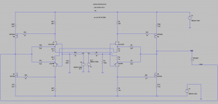
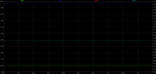
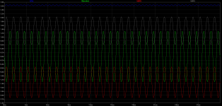
Attached is the circuit. I adjusted feedback to get a gain of 5 to make it easy on me. There is nothing special about it.
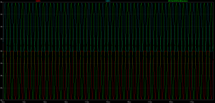
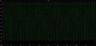
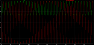
I also have attached the results with 0V sig. You can see the current running through both sides is equal (ie 1.3A) and the current drawn from the power supply is 2.6A (1.3 + 1.3 = 2.6). We will ignore (pretend it does not exist) the 0.007A + 0.007A runnning through the Jfets to make things easy on ourselves.
Attached is the circuit. I adjusted feedback to get a gain of 5 to make it easy on me. There is nothing special about it.
I also have attached the results with 0V sig. You can see the current running through both sides is equal (ie 1.3A) and the current drawn from the power supply is 2.6A (1.3 + 1.3 = 2.6). We will ignore (pretend it does not exist) the 0.007A + 0.007A runnning through the Jfets to make things easy on ourselves.
Attachments
Melon Head and AndrewT, thanks. I hesitate to jump into this Balanced stuff before we help out everyone who has questions and or confussion about the single ended version. It's tough enough thinking in a manor to explain it well.
It might be good if we go to the wikipedia again and search on balanced line. This balanced bisness is more complicated than just an amp with 2 inputs. It's really an impeadance controled (balanced) differential system. We likely are misusing the term somewhat? We possibly should be calling this thing a differential version or something? As in most differential amps you will be amplifying the difference between 1 input and the other without refrence to ground. In a balanced system the pin 1 on the xlr is a sheild, not signal ground.
Melon Head, where did all that come from? While I was typing?
Last edited:
- Status
- This old topic is closed. If you want to reopen this topic, contact a moderator using the "Report Post" button.
- Home
- Amplifiers
- Pass Labs
- Balanced F5 question