This is what Juma posted on "baby DIYA" (copyright Zen Mod ") ) introducing the updated version:
) introducing the updated version:
Prica se nastavlja...Proslo je neko vreme, izvrtele se jos neke konstrukcije, ali ostao je utisak da je ovaj amp "the end of the road". Medjutim, posto djavola jos uvek mrzi da ore i kopa, uze da me gnjavi - dal' bi to moglo jos malo bolje ? I moze !Zadatak je bio bude nesto neznije, zavodljivije, mekse ali sa istom detaljnoscu i besprekornom, prirodnom reprodukcijom. Evo kako je uspelo: - napajanje je promenjeno utoliko sto ga cine dva istovetna mnozaca kapaciteta sa IRFP044N (izabran zbog sjajne strujne sposobnosti, brzine i transkonduktanse) vezana na red (ovako se postize i veca simetrija u radu jer su oba MOSFETa jednaka) i posle njih su dodati mnogo veci kondovi (33.000uF/35V Panasonic, iz GB). Ripple je manji od 1mV p-p pri 2.5A opterecenja.- izlazni stepen ima nesto vecu degeneraciju Source-a (0R68 umesto 0R33) , GNFB je smanjena, odnosno gain je veci (8.5 umesto 5.5 V/V). Interesantno je da ukupna linearnost nije ostecena, toliko su dobri ovi Toshibini MOSFET-ovi. Ova dva faktora treba nezno uskladiti jer ako se pretera na bilo koju stranu javlja se ili nesto manje prirodna (kako kazu, "organska") reprodukcija, ili postane suvise meka, nalik na brojne cevne amp-ove, sa brljanjem u kompleksnim pasazima (orkestarska kresenda i sl.)Sve ostalo je prilicno isto.
OK, it's in Serbian, but G. Translator may let you understand.
) introducing the updated version:Prica se nastavlja...Proslo je neko vreme, izvrtele se jos neke konstrukcije, ali ostao je utisak da je ovaj amp "the end of the road". Medjutim, posto djavola jos uvek mrzi da ore i kopa, uze da me gnjavi - dal' bi to moglo jos malo bolje ? I moze !Zadatak je bio bude nesto neznije, zavodljivije, mekse ali sa istom detaljnoscu i besprekornom, prirodnom reprodukcijom. Evo kako je uspelo: - napajanje je promenjeno utoliko sto ga cine dva istovetna mnozaca kapaciteta sa IRFP044N (izabran zbog sjajne strujne sposobnosti, brzine i transkonduktanse) vezana na red (ovako se postize i veca simetrija u radu jer su oba MOSFETa jednaka) i posle njih su dodati mnogo veci kondovi (33.000uF/35V Panasonic, iz GB). Ripple je manji od 1mV p-p pri 2.5A opterecenja.- izlazni stepen ima nesto vecu degeneraciju Source-a (0R68 umesto 0R33) , GNFB je smanjena, odnosno gain je veci (8.5 umesto 5.5 V/V). Interesantno je da ukupna linearnost nije ostecena, toliko su dobri ovi Toshibini MOSFET-ovi. Ova dva faktora treba nezno uskladiti jer ako se pretera na bilo koju stranu javlja se ili nesto manje prirodna (kako kazu, "organska") reprodukcija, ili postane suvise meka, nalik na brojne cevne amp-ove, sa brljanjem u kompleksnim pasazima (orkestarska kresenda i sl.)Sve ostalo je prilicno isto.
OK, it's in Serbian, but G. Translator may let you understand.
IRFP044N (izabran zbog sjajne strujne sposobnosti, brzine i transkonduktanse)
IRFP044N (chosen because of great current capability ,speed and xconductance)
also - he said he chose same mosfet sex in both PSU legs to achieve better symmetry
That is a good argument for the topology, but doesn't give insights as to
why the IRFP044 would be the transistor of choice.
That's a good point. If we just go by Vgs and transconductance,
then perhaps something like IRFB8743
http://www.infineon.com/dgdl/irlb8743pbf.pdf?fileId=5546d462533600a4015356605d6b2593
is worth trying (lower Vgs and even higher transconductance)
Dennis
For lower voltage circuits, the PSMN1R025YLD with 1mOhm Rdson may even be better?
http://datasheet.octopart.com/PSMN1R0-25YLD-NXP-Semiconductors-datasheet-62336464.pdf
http://www.diyaudio.com/forums/soli...asy-capacitance-multiplier-3.html#post4855716
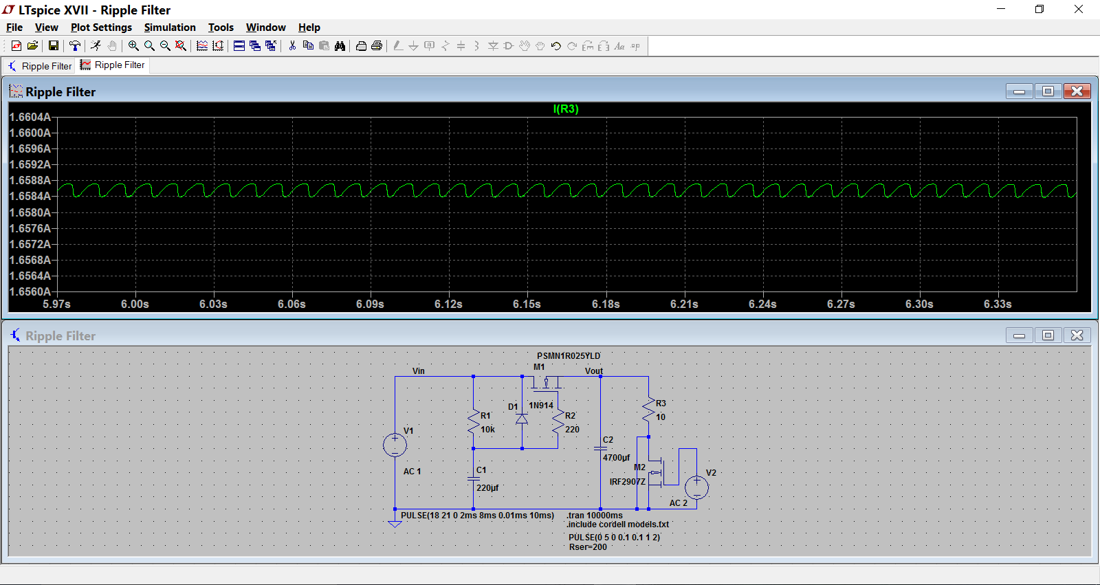
Here is Mooly's sim for 1.7 amps steady state:
http://datasheet.octopart.com/PSMN1R0-25YLD-NXP-Semiconductors-datasheet-62336464.pdf
http://www.diyaudio.com/forums/soli...asy-capacitance-multiplier-3.html#post4855716
Here is Mooly's sim for 1.7 amps steady state:
IRFP044N (chosen because of great current capability ,speed and xconductance)
also - he said he chose same mosfet sex in both PSU legs to achieve better symmetry
Thank you ZM!
Viva Vale, WLF
adding another 2 cents to the translation cause:
in the mkII amp version Juma also "increased source degeneration in the output (0R68 instead of 0R33) thus reducing GNFB and increasing gain from 5.5 to 8.5V/V. the overall linearity however did not suffer since these Toshiba fets proved that great." end of quote
in the mkII amp version Juma also "increased source degeneration in the output (0R68 instead of 0R33) thus reducing GNFB and increasing gain from 5.5 to 8.5V/V. the overall linearity however did not suffer since these Toshiba fets proved that great." end of quote
Last edited:
Hmm... I am running 0.22R degeneration resistors because I have no 0.33R on hand. Should I try 0.47R? I am already at 20dB gain by using 100R vs 50R FB resistors. Maybe change that back to 50R (via paralleld 100R's)? Although I have to say that the sound quality and speaker measuremts showed some of the lowest distortion levels in any of my amps.
In any case, I am just saying to folks who have not tried the cap multiplier to try it. It works very well and is so simple.
In any case, I am just saying to folks who have not tried the cap multiplier to try it. It works very well and is so simple.
Finally Getting Started
Well, I checked into this thread 3 years ago, but now FINALLY about to start.
I got all the FETs from Spencer, and Prakit who built a line amp earlier in this thread.
I just bought a case on Ebay. Looks pretty nice! Ebay Item 142090474294
Got a power supply- yes its SMPS so what, I'm trying it. Its a Vicor Flatpak, and I think pretty nice. We'll see how it sounds.
Also, got Permaneder's board through Nik_D who an extra set.
So ready to go! Have a few questions though.
Could someone look through my attached BOM? I pieced it together from the main F5 thread, and some other sources, but I'm not sure of some of my part selection. Especially the source .33R resistors. Someone recommended the Fukishima MPC70, but I can't find them. I'm looking for something readily available on Digikey or Mouser. Also, if anyone has any other recommendations for resistors, I'd love to hear.
My other question is that I was going to use a Shunt style stepped attenuator, so I was thinking of using R1 as the series resistor of the attenuator, and R2 as the shunt. R1 would be about 10K and R2 would range from 50R to probably 15K. Any issues with that impedance-wise?
Attachments
As koja said above, the increased degeneration resistors from 0.47 -> 0.68 is all to do with the 'sound signature' - with 3 output pairs running at between 0.4 <-> 0.5A per device, the resistor can be a 1 watt components, but 2w one for comfort - suggest KOA for a 'softer' sound but many options
You might find benefit adding one of those C-multipliers after the Vicor supply too - best bang for the buck around
Attenuator - suggest you build the amp first, get it up and running, then play with attenuators - and this will be before the input gain stage (the 'prakit' project?) and will have it's own optimal settings - I've had great success with Uriah's 'Clone Note' for volume control and suggest a look ...
the current limit for a 2W 0r47 resistor is sqrt(2W/0.47r)=2.06Arms.with 3 output pairs running at between 0.4 <-> 0.5A per device, the resistor can be a 1 watt components, but 2w one for comfort
Three pair output stage allows 6.2A if the source resistors were working at 100% duty cycle.
But a push pull amplifier runs the source resistors between 50% and 70%. so your maximum output current will be ~9A to 12A
This is OK for a 50W into 8ohms amplifier.
I think for a 4ohms amplifier you need bigger resistors or lower value resistors to reduce the dissipations.
You should not size the source resistors based on quiescent currents alone.
MPC74 should be a little better (low distortion type)Especially the source .33R resistors. Someone recommended the Fukishima MPC70, but I can't find them.
If you really want them, drop an email to this company in Taiwan https://thlaudio.com/indexE.htm
They do have them in stock
Using Nelson as an authority, with 0.47R as source resistors, peak current is about 3.5A for ambient 1.5A - for 0.68R's, this reduces to about 2.5A peak but assuming the higher value, the power thru each source resistor will be about 1.2A X 1.2A X 0.68R = approx. 1W, and this is peak value so a 2W source resistor is perfectly adequate.
My 0.68R 2W ones have been doing good service for the last few years with the amp (original F5juma Mk II version) biased at a bit under 1.5A and the resistors only get hot in mid summer - if you use the Caddock mp915, they did get hot but are only rated about 1W but their bigger brothers, the MP930 that are rated about 2W (@ 40*C derated) just got quite warm (not my favourite in this cct but readily available) - so you can relax a bit on the power ratings recommended by some people - if it's a problem accessing the values, try 1R0, 2W in // with 2R0, 1W for the 0.68, etc, etc
From memory, Passlabs still use Panasonics power resistors - maybe this is good enough for you?
Mouser keep a variety of Koa (Speer) and have carbon's, metal film, met oxide, planar, smd, etc - you can use the bigger 2W smds by attaching copper wire legs - be creative!
I use Issabellenhutte when values finalised but hard to get, or make my own with Manganin wire but a bit of a PIA.
Thanks for everyone's feedback and for this: https://thlaudio.com/indexE.htm
I think I'll pick up the MPC70's from there, and go with the 0r68 value as well.
I'm shooting for the most "relaxed" sounding version I can get from the F5 topology, and reading the main F5 thread, it seems lowering the feedback can help.
If I go with one 100r resistor in each feedback location instead of two parallel, do I need to change R3 and R4 to 0r22, as is mentioned in the main F5 thread?
Also, if I go with just one 100r resistor, would I have to increase the wattage of that resistor to more than a 2W resistor?
Last edited:
Here's the link to the main F5 thread mentioning to change the 0r10 to 0r22 if feedback decreased:
http://www.diyaudio.com/forums/pass-labs/121228-f5-power-amplifier-374.html#post1831285
http://www.diyaudio.com/forums/pass-labs/121228-f5-power-amplifier-374.html#post1831285
F5 Juma with 5 pairs
Hi Juma
better later than never but I decided to try your amp
I really like to Improve rough signature of my original build F5 running with FQA Fets on 1.6A bias and 23V
I bought a permaneder 5 pair pcb http://www.diyaudio.com/forums/pass-labs/168040-f5-2sk2013-2sj313-35.html#post4920144 , thank you Djordje
I like to try It with 23 V rails and 0.37A per device current which give total of 1.85 A bias and 8.5 W dissipation per Mosfet
Would you approve such use, would you please recommend your choice for source resistor values and feedback resistors - can I use 0.47 Mills resistors Instead off 0.33 value
In case of difficulties obtaining k2013/j313 Is It possible to use FQP3 devices
It's OK: 0R47 Rs, 23V rails (I suppose that's with cap. multiplier).
Try 3 output pairs at first and then add another pair and see if you hear the difference. If you are OK with that try adding the 5th pair and see what you get and whether you still like it. More output MOSFETs means more parasistic capacitance to drive. Total transconductance will be higher too, but you'll have to test it to see if it sounds good to you.
+/-20V rails, cap multiplier, 0R33 Rs and 3 pairs were optimal configuration for me.
FQP3 devices will work but I didn't test how the amp sounds with them.
OK, after you add cap. multiplier to your PSU you'll have about +/-19V rails.
You can put as many output pairs as you wish but I find that 3 pairs is optimal - you should experiment and find out how many pairs makes you happy..
There is a sound difference between different RS values - 0R33 sounds more expressive and 0R68 is more forgiving to non-perfect recordings. Test and find out what you prefer.
- Status
- This old topic is closed. If you want to reopen this topic, contact a moderator using the "Report Post" button.
- Home
- Amplifiers
- Pass Labs
- F5 with 2SK2013/2SJ313