5r is the value difference that Euvl adopted.
i.e. 10r in the k170 source and 15r in the j74 source, if my memory is still right.
The sliding bias offered by the pot//fixed resistors, achieves the same thing by letting the two N & P see different r values to audio ground.
i.e. 10r in the k170 source and 15r in the j74 source, if my memory is still right.
The sliding bias offered by the pot//fixed resistors, achieves the same thing by letting the two N & P see different r values to audio ground.
5r is the value difference that Euvl adopted.
i.e. 10r in the k170 source and 15r in the j74 source, if my memory is still right.
The sliding bias offered by the pot//fixed resistors, achieves the same thing by letting the two N & P see different r values to audio ground.
Your memory is correct about the resistor values used by EUVL. I actually employ a set of values as this increases the yield of K170/J74 that can be matched to trace perfectly.
Of course, if Nelson's "P3" pot//fixed resistors achieves exactly the same thing in adjustable way then I will rest my case.
10r + 10r and then a parallel 100r with the wiper connected to the 10r junction is exactly equivalent to 10r//50r in the source of each jFET, when the pot is set to exactly half way.
10r//50r = 8r3333.
Now move the wiper up towards the NjFET.
The upper resistance becomes 10r//40r = 8r0 and the lower resistance becomes 10r//60r = 8r571
Go a bit further:
10r//30r and 10r//70r gives upper and lower Rs = 7r5 & 8r75
and further 10r//20r with 10r//80r gives Rs = 6r667 & 8r889
and further 10r//7r with 10r//93r gives Rs = 4r118 & 9r029 (getting very close to that 5r difference).
Personally I would adopt 12r+12r and parallel that with 5r+200VR+5r giving 12r//105r (=10r8 at the midway setting). This avoids setting Rs to zero and avoids setting the Rs of either jFET rather low (which increases the Id and thus heat).
Ok - so either a pot over R3/R4 (like permaneder had) or 0805 SMD solder pads right on the J74 source leg (i.e. in series with R4, but outside of the feedback loop). I personally prefer the latter. Of course the inductor and fan regulator provisions is of no importance to me...
I'm not the designer so obviously not my choice")
P.S. The mosfet source resistors I would use are Caddock MP930 series. Not cheap but also non-inductive.
I'm not the designer so obviously not my choice
P.S. The mosfet source resistors I would use are Caddock MP930 series. Not cheap but also non-inductive.
Nick- take my BOM that I posted a few posts back. Make whatever changes to it you would like. If you can find me a part # that I can get here in the US, I'd be happy to make the changes. For my BOM, I cobbled that together from some other standard F5 BOM's I found circulating, so its only slightly better than arbitrary. It seems you have put more thought into your selections, so I'm happy to improve things based on your recommendations.
I think I'd prefer to add the extra smd resistor rather than a pot, since I am not going that extra step to match the curves on the jfets. I ordered matched pairs, so I'm taking the leap of faith that they are matched enough for me
I think I'd prefer to add the extra smd resistor rather than a pot, since I am not going that extra step to match the curves on the jfets. I ordered matched pairs, so I'm taking the leap of faith that they are matched enough for me
Your memory is correct about the resistor values used by EUVL. I actually employ a set of values as this increases the yield of K170/J74 that can be matched to trace perfectly.
Of course, if Nelson's "P3" pot//fixed resistors achieves exactly the same thing in adjustable way then I will rest my case.
Not for all k170/j74, no. But may be for the ones I use.do you know that k170/j74 will always need any Rs difference to equalise their gm?
Yes - he won'tdo you know if the builder will substitute another pair of jFETs?
In any case, I get your point. Thanks.
Sven
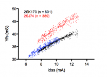
If you have Idss-matched K170/J74 (which is what I think Spencer sells) they will never have the same gm. If the J74 are degenerated they may achieve equal gm and even equal Idss if well selected as shown in the figure I have attached (blue are the 5R1 degenerated J74).
Attachments
Ok - so either a pot over R3/R4 (like permaneder had) or 0805 SMD solder pads right on the J74 source leg (i.e. in series with R4, but outside of the feedback loop). I personally prefer the latter. Of course the inductor and fan regulator provisions is of no importance to me...
I'm not the designer so obviously not my choice
P.S. The mosfet source resistors I would use are Caddock MP930 series. Not cheap but also non-inductive.
Do you need to heatsink those Caddocks? (ie. would they have to be placed along the edge of the board, for that purpose?) I may or may not choose to use the Caddocks as well (pricey!), but I could at least add another trace with the appropriate footprint, so at least there is choice.
Back to the 10R R3, and R4 + degenerative resistor. The particular resistors I used there are rather jumbo 1W through holes. Really, I didn't think too much about them- rather just copied from a stock F5 BOM I found. But in thinking about it, that seems to be way overkill in power rating. How about I change both of those to 1/8th watt 0805 smd's (+ the degenerate in series)?
Ok - so either a pot over R3/R4 (like permaneder had) or 0805 SMD solder pads right on the J74 source leg (i.e. in series with R4, but outside of the feedback loop). I personally prefer the latter. Of course the inductor and fan regulator provisions is of no importance to me...
I'm not the designer so obviously not my choice
P.S. The mosfet source resistors I would use are Caddock MP930 series. Not cheap but also non-inductive.
If there is sufficient interest, I would order another run of my boards. Provided that we use the initial layout without any changes, we would have a price of less than EUR 25 (~USD 32) per set from a volume of 25 sets onwards (otherwise my board makers charge ~EUR 35 preparation cost for the new board). International shipment by registered first class mail is EUR 6.50 (~USD 8.40) including a padded envelope.
Using the caddocks doesn't cause any problem - just bend their legs a bit (their spacing is 5.08mm versa 8mm of the Fukushima MPC78).
Attachments
10r + 10r and then a parallel 100r with the wiper connected to the 10r junction is exactly equivalent to 10r//50r in the source of each jFET, when the pot is set to exactly half way.
10r//50r = 8r3333.
Now move the wiper up towards the NjFET.
The upper resistance becomes 10r//40r = 8r0 and the lower resistance becomes 10r//60r = 8r571
Go a bit further:
10r//30r and 10r//70r gives upper and lower Rs = 7r5 & 8r75
and further 10r//20r with 10r//80r gives Rs = 6r667 & 8r889
and further 10r//7r with 10r//93r gives Rs = 4r118 & 9r029 (getting very close to that 5r difference).
Personally I would adopt 12r+12r and parallel that with 5r+200VR+5r giving 12r//105r (=10r8 at the midway setting). This avoids setting Rs to zero and avoids setting the Rs of either jFET rather low (which increases the Id and thus heat).
As I recall, Nelson only twisted the pot a small amount and used a distortion analyzer to set. I believe he said without a way to measure the distortion, you should just leave it in the center.
The pot changes the feedback per bank where as the 5 ohm resister is placed above the point where the feedback is inserted. There is a schematic on this page:
http://www.diyaudio.com/forums/pass-labs/121228-f5-power-amplifier-950.html#post2409557
The 5 ohm is the way to go for most of us.
Also, there is a formula for figuring the Idss for value of the J74 vs the K170, I think he was using it for 2SK1530/J201 in a balanced FX5. http://www.diyaudio.com/forums/pass-labs/172770-balanced-f5-question-55.html#post2364264
Pretty sure it will work for a regular F5, but someone should ask EUVL.
Rush
Ok - so either a pot over R3/R4 (like permaneder had) or 0805 SMD solder pads right on the J74 source leg (i.e. in series with R4, but outside of the feedback loop). I personally prefer the latter. Of course the inductor and fan regulator provisions is of no importance to me...
I'm not the designer so obviously not my choice
P.S. The mosfet source resistors I would use are Caddock MP930 series. Not cheap but also non-inductive.
NicMac,
In my BA3b, I have simply added pads for smd resistors to replace the pot when the final setting is reached. Unless you are starting with dissimilar IDSS ratings for the Jfets, there is absolutely no reason it would not work in the same way.
Thank you for locating these links. In the white paper where EUVL describes this trick he say that it will work just fine with a stock F5. However, as far as I know only the EUVL F5X boards have provisions for this degeneration resistor. All the F5, F5c, F5T, F5 Juma etc. boards that I know are not predisposed for this Rdeg so trace cutting or the likes in the only way to goPretty sure it will work for a regular F5, but someone should ask EUVL.
Rush
Thank you for locating these links. In the white paper where EUVL describes this trick he say that it will work just fine with a stock F5. However, as far as I know only the EUVL F5X boards have provisions for this degeneration resistor. All the F5, F5c, F5T, F5 Juma etc. boards that I know are not predisposed for this Rdeg so trace cutting or the likes in the only way to go
OH, don't let that stop you. We are DIYers, just bend one leg of the J74 and solder a 5 ohm resistor from there is the hole. Easy peasy.
Rush
Thank you for locating these links. In the white paper where EUVL describes this trick he say that it will work just fine with a stock F5. However, as far as I know only the EUVL F5X boards have provisions for this degeneration resistor. All the F5, F5c, F5T, F5 Juma etc. boards that I know are not predisposed for this Rdeg so trace cutting or the likes in the only way to go
It's easy to change the board to whatever you like. Would raise the cost per set a bit however (~ EUR 1.50 @ an order volume of 25 sets)
It's easyto change the board to whatever you like. Would raise the cost per set a bit however (~ EUR 1.50 @ an order volume of 25 sets)
Whatever I like
I would really like the best of both Pass's, EUVL's and Juma's worlds
An EUVL style F5X PCB with Juma's modifications including provisions for 4 parallel K2013/J313 in place of each K1530/J201
I know only few are interested in balanced audio gear and I know it is a lot of mosfets (16 of each), but as you might have noted I have plenty of these
I would be happy to share manufacture cost if somebody was to design such a PCB (top quality - of course!). Actually, I would even add a curve traced NNNNNNNNNNNNNNNNPPPPPPPPPPPPPPPP-set of K2013/J313 and a degeneration matched NNNNPPPP-set of K170/J74..............
Of course getting to 25 boards might be a problem
I think I have matched 2SK2013, 2SJ313, 2SK170 and 2SJ74 enough for 25+ amps (50 PCBs.....)
I just need a first-class circuit and PCB design
But remember this would not be a Turbo. I think it would deliver an amazing "First Watt" and above that have power line an ordinary F5.....
But then some of us are after better - not more
I just need a first-class circuit and PCB design
But remember this would not be a Turbo. I think it would deliver an amazing "First Watt" and above that have power line an ordinary F5.....
But then some of us are after better - not more
- Status
- This old topic is closed. If you want to reopen this topic, contact a moderator using the "Report Post" button.
- Home
- Amplifiers
- Pass Labs
- F5 with 2SK2013/2SJ313