Finally, my Mosfets have arrived from Utsource. Now begins the hunt for 2sj74s. In the meantime, I might even try 2N5461 for the P-channel JFET and try out the amp.
Just two questions, should the 4K7 NTCs be disc type or screw-type and if discs, should they be in contact with the heatsink?
Will a bias of 1.6Amps be O.K. for 4 pairs of Output devices at rail voltage of + -20 Volts?
I have 18-0-18 volt 160VA torroids that I am planning to use with Juma's published Cap multipliers. Thanks.
Sam,
To my mind 160va is less even for 1 channel, but for 2 channels, definitely not enough. The transformer will start heating up as well may be hum.
18-0-18 secondaries will yield around 25-24v after bridge and capacitors per rail. It will not be 20v unless I am missing something that you wrote.
You can get enough and more 2sj74BLs on eBay. There are some reliable suppliers as well. You may need to match them yourself.
Another thing that I would alert is about heatsinks. Do not underestimate their requirement in terms of heat dissipation and size. F5 can become quite hot.
Cheers.
Thanks to everyone for their very useful inputs.
I meant that I would use 18-0-18volt 160VA torroids - one for each channel, simply because I have them already.
O.K. I set about to design a PCB for the amp and when it came to the input and feedback ground, I was wondering if the amp could benefit from a quiet ground ie., ground lifted off the main ground (PSU and Output) by a 10E resistor and 2 anti-parallel diodes? Also I do not see any coupling caps shown in the amp schematic nor after the cap multiplier, but I plan on using some electrolytics plus one 10uF MKT close to each output device' source resistors. Any inputs on this issue?
Samuel,
I'd suggest as you're doing a pcb for the 3, or 4, o/p pairs that you add a few things for flexibility.
1. Add a extra resistor for j74 jfet degeneration - can 'jumper' it easily if not required.
2. Add the ability to use different jfet gate stoppers - suggest jackinnj version as per standard F5 thread post either 918, 956, 984, 1038.
3. Add extra resistors across R13,R14,R15 to trim the fet source resistors for the unequal Yfs of the o/p fets. Also, add 10mm holes for possible use of Caddock, etc plate resistors.
Nothing new here, been discussed quite a bit, nice to add the flexibility when you're developing the pcb - possibly, do a small pcb for the Cmultiplier to mount on the heatsink next to the main pcb - short wires, etc
AFAIK Caddock TO220 resistors requires 0.2 in or 5.8 mm spaced holes, while MPC74/78 Fukishima or similar plate resistors 9 mm... Also, add 10mm holes for possible use of Caddock, etc plate resistors.
0.2"=5.08mm centre to centre.AFAIK Caddock TO220 resistors requires 0.2 in or 5.8 mm spaced holes,
"spaced" can be ambiguous and be read as the gap between the holes.
I believe in an earlier post Nelson implied that decoupling caps near the outputs devices were not to be used. I can't find the post but seem to rember him saying
something like did you see any decoupling caps in the circuite drawing ?
Now that's interesting and unconventional. But I guess, decoupling caps near the output devices may slow down the speed of sonic presentation raved by so many in the F5 thread as well as colour the sound. In fact, the sound of many amps can be tweeked by this method.
Another interesting feature, is that the F5 has no tendency to oscillate and does not need decoupling caps on the amp board. Wow!
However, since this is a slightly different implementation of the original F5, I'll keep the option open and see how it goes; particularly so, because the amp is preceded by a cap multiplier.
Matching 2SK2013 / 2SJ313 HELP! PLEASEEEE
Hi,
Can anyone point me to the right direction on how to match those transistors?
I'm not a master electronician but understand pretty fast!
All I have right now is a very good DVM but no oscilloscope (although I have friends that have).
Do I need to build a simple circuit to test them?
Procedure?
I have to be between 2-3%
Again this is really appreciated!
Thanks
Do
Hi Pinnocchio
I have been doing a bit of work on matching FQA19N20
Papa published a guide
Frag Bridge and its other posts are quite good as well.
Tendency is to say that matching at working parameters is best.
To which I agree but also test at different settings just to reduce the number of dudas I will have to test at working conditions
I suppose you will just need a larger resistor to reduce the current and use same way to keep an eye on it or you get smoke.
May be worth investing on a cheap meter just for this
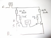
I am posting a crappy drawing of the Frags Bridge as you see I use a meter for the current (cheap and nasty) and a better one for the voltages
When you get started you will notice that VGS changes with temperature by bolting the 2 mosfets close to each other the change in temperature cancel out.
More in my post
Ps takes what I say with a pinch of salt I am new to the 3-leghed kind. Loads of peoples that place 30 40 post a day may know better and have read all the books.
Hope this get you started
Al
I have been doing a bit of work on matching FQA19N20
Papa published a guide
Frag Bridge and its other posts are quite good as well.
Tendency is to say that matching at working parameters is best.
To which I agree but also test at different settings just to reduce the number of dudas I will have to test at working conditions
I suppose you will just need a larger resistor to reduce the current and use same way to keep an eye on it or you get smoke.
May be worth investing on a cheap meter just for this
I am posting a crappy drawing of the Frags Bridge as you see I use a meter for the current (cheap and nasty) and a better one for the voltages
When you get started you will notice that VGS changes with temperature by bolting the 2 mosfets close to each other the change in temperature cancel out.
More in my post
Ps takes what I say with a pinch of salt I am new to the 3-leghed kind. Loads of peoples that place 30 40 post a day may know better and have read all the books.
Hope this get you started
Al
Attachments
Hi
Not shure about your mosfets as smaller than the FQA I am testing
Is this version of the F5 specified at 0.5A 16 V ?
If so thats the answer you were looking for ?
Would start with 15 V and 20 ohms maybe but don't blame me if you smoke them as I don't have any of those to try for you.
Beter safe than sorry so half the V or duble R and maybe you be ok to start
15 V 10 ohms works vell enough for the FQA as I get 1.1 A but the treshold curent of your mosfet may be lower
Papa paper is a good source of information (and enjoible to read) well wort looking at it does answer loads of questions.
Frags diagrams are quite good Just start with low voltage to the gate and take it easy
- Status
- This old topic is closed. If you want to reopen this topic, contact a moderator using the "Report Post" button.
- Home
- Amplifiers
- Pass Labs
- F5 with 2SK2013/2SJ313