Transformer and caps look OK, so it must be something else in PSU - I don't know what diodes you use, how much is a cap multiplier drop, do you have any serial resistor in PSU, what is the ESR of your caps, and so on...
When it comes to temperature, difference of 5 degrees C between MOSFETs and heatsink is OK, more than that is no good - check your keratherm, paste, etc...
When it comes to temperature, difference of 5 degrees C between MOSFETs and heatsink is OK, more than that is no good - check your keratherm, paste, etc...
Last edited:
Measurements
I built this amp about a year ago, and have been really enjoying it. See post here:
http://www.diyaudio.com/forums/pass-labs/168040-f5-2sk2013-2sj313-73.html#post5169846
I just picked up a QuantAsylum QA400 from another member, so this is the first time I've ever done measurements. The input of this device only allows a 2Vrms input, and I didn't have any voltage divider resistors on hand, so all measurements were done at low level, very carefully, with a 7.5R 5W resistor.
So, these are all around 1/2W - 1W output. I'll get some resistors and measure again at higher wattages.
I took a frequency response, as well as a 1 kHz and 10 kHz measurements.
Some notes:
Let me know if it looks like I did this correctly. If I did, I'm pretty impressed! All harmonics are down at -90 or -100dB, I think not bad!
Thoughts?


I built this amp about a year ago, and have been really enjoying it. See post here:
http://www.diyaudio.com/forums/pass-labs/168040-f5-2sk2013-2sj313-73.html#post5169846
I just picked up a QuantAsylum QA400 from another member, so this is the first time I've ever done measurements. The input of this device only allows a 2Vrms input, and I didn't have any voltage divider resistors on hand, so all measurements were done at low level, very carefully, with a 7.5R 5W resistor.
So, these are all around 1/2W - 1W output. I'll get some resistors and measure again at higher wattages.
I took a frequency response, as well as a 1 kHz and 10 kHz measurements.
Some notes:
- On the left channel, I did a better job matching the FETs. The right channel has one slight outlier. I suppose this is this reason for the slightly better measurements of the left channel?
- Frequency response looks pretty good! I put some capacitors across the feedback resistors as NP had suggested. Maybe this accounts for the declining response above 30kHz? Not that it matters- but I believe the F5 is flat out to 500kHz otherwise.
Let me know if it looks like I did this correctly. If I did, I'm pretty impressed! All harmonics are down at -90 or -100dB, I think not bad!
Thoughts?

Good luck Nisbeth. Let me know how hot your mosfets are when you'll get it up and running ")
I've got mine playing since yesterday and it easily sounds better than anything that I've ever had, albeit this is not terribly difficult threshold to cross.
BTW, I did not mention this yet, I'm using GR grade JFETs @5.1mA, as suggested earlier by Juma. They were easier to get than BLs.
I've got mine playing since yesterday and it easily sounds better than anything that I've ever had, albeit this is not terribly difficult threshold to cross.
BTW, I did not mention this yet, I'm using GR grade JFETs @5.1mA, as suggested earlier by Juma. They were easier to get than BLs.
Last edited:
... I'm using Kerathem 86/82 for thermal coupling...
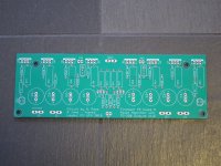
If you use 2sk2013/2sj313 in your amp (like one shown in image below) you don't need keratherm or any other insulator pads - these MOSFETs have insulated case and you shouldn't insert additional thermal resistance between them and the heatsink - a rice grain of thermal paste is all you need.

Last edited:
Looks OK - it's only that noise is more prominent, but that's your SMPS, I suppose...I built this amp about a year ago...
Let me know if it looks like I did this correctly. ...
If you use 2sk2013/2sj313 in your amp (like one shown in image below) you don't need keratherm or any other insulator pads - these MOSFETs have insulated case and you shouldn't insert additional thermal resistance between them and the heatsink - a rice grain of thermal paste is all you need.
Kerathem is not being used there for insulating purposes but to transfer heat efficiently. This particular Kerathem Red has heat conductance of 6.5 W/mK so I don't think I'll exchange it for a paste which, as far as I'm aware, has lower heat conducting properties, unless there is a paste available with conductance > 7W/mK?
I have ordered a pirometer from Amazon already so I'll be able to quantify my question soon. So far my portable weather station (the only temperature sensor that I have at hand as of now ...) shows the temperature of the heat sink at below 50 deg C, which is very similar to your findings published in post #5 if I read it correctly?
Also: Keratherm Transistor Insulators – diyAudio Store
Let me know if it looks like I did this correctly. If I did, I'm pretty impressed! All harmonics are down at -90 or -100dB, I think not bad!
Thoughts?
View attachment 696763
Is that graph "inconsistency" visible above 40-50kHz, the result of audio analyser quantization noise?
Last edited:
- Status
- This old topic is closed. If you want to reopen this topic, contact a moderator using the "Report Post" button.
- Home
- Amplifiers
- Pass Labs
- F5 with 2SK2013/2SJ313