Progress on P2P F5 J313/K2013
I just finished building and now need to test. Debating whether or not to test now or wait until fresh eyes tomorrow...
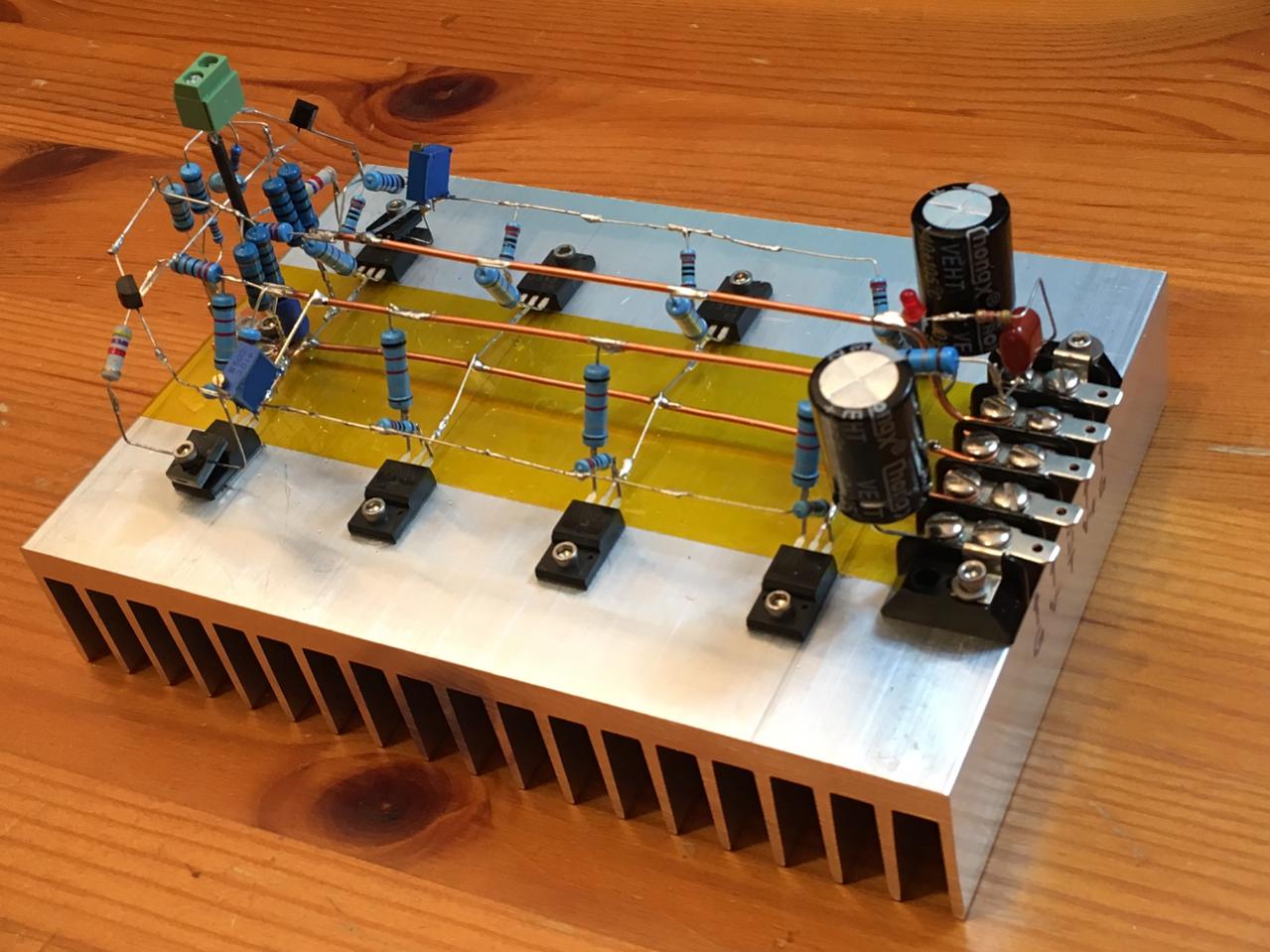
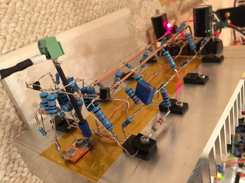
I don't have any 4.7k NTC thermistors on hand yet (on order). I put a carbon 4.7k resistor in place and added a 1N4007 diode in series. Si has a negative tempco and I clamped the diode onto the MOSFET body. I did not have any 0.33R 2W resistors so am using 0.22R 2W metal thin films.
I also added 2200uF smoothing caps on the rails, and a 10R-100nF to ground Zoebel on the output as customary with most of my amps.
It was fun and not too hard. I hope it works.
I just finished building and now need to test. Debating whether or not to test now or wait until fresh eyes tomorrow...
I don't have any 4.7k NTC thermistors on hand yet (on order). I put a carbon 4.7k resistor in place and added a 1N4007 diode in series. Si has a negative tempco and I clamped the diode onto the MOSFET body. I did not have any 0.33R 2W resistors so am using 0.22R 2W metal thin films.
I also added 2200uF smoothing caps on the rails, and a 10R-100nF to ground Zoebel on the output as customary with most of my amps.
It was fun and not too hard. I hope it works.
Attachments
Last edited:
 Hope it works and sounds as expected also.
F5 J313/K2013 P2P singing now
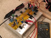
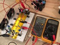
It works! Adjusting bias/offset was tricky. The bias changes a lot for a small movement of the pot so I am not sure why it is so sensitive. I think the diode temp compensations is even working. Running at about 1.6amps total current. Sounds real nice - clear and delicate sounding.
Here it is showing 60mV across 0.22ohms Source resistor or 273mA on one MOSFET. About 54W dissipation overall.
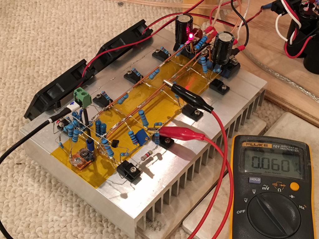
Here is a closeup of the input stage:
It works! Adjusting bias/offset was tricky. The bias changes a lot for a small movement of the pot so I am not sure why it is so sensitive. I think the diode temp compensations is even working. Running at about 1.6amps total current. Sounds real nice - clear and delicate sounding.
Here it is showing 60mV across 0.22ohms Source resistor or 273mA on one MOSFET. About 54W dissipation overall.
Here is a closeup of the input stage:
Attachments

Last edited:
One of the 2SK2013's is running hot passing, 1.1amps through the 0.22R Source resistor, while the others are 300mA. Is it defective or is this just the whole reason why we need to match them? Seems to be quite the outlier and the others are sort of in same ballpark.
I think I have a schematic somewhere on how to test them with a 9v psu and an ammeter.
I think I have a schematic somewhere on how to test them with a 9v psu and an ammeter.
How closely did you match the source resistors?One of the 2SK2013's is running hot passing, 1.1amps through the 0.22R Source resistor, while the others are 300mA. Is it defective or is this just the whole reason why we need to match them? Seems to be quite the outlier and the others are sort of in same ballpark.
I think I have a schematic somewhere on how to test them with a 9v psu and an ammeter.
That makes a difference.
a.) matched resistors allows comparison of current flow.
b.) matched resistors gives a matched voltage drop when the current is equal.
Yes, see post #369
"...I added Papa's "tone control", a 200R trim pot paralleled to the 10R Source Rs of the JFETs (optional)..."
"...I added Papa's "tone control", a 200R trim pot paralleled to the 10R Source Rs of the JFETs (optional)..."
I see that there is a 200R pot in the middle. Can someone point me to hweee this schematic is? Is that the H2/H3 "dial a distortion knob"?
How closely did you match the source resistors?
That makes a difference.
a.) matched resistors allows comparison of current flow.
b.) matched resistors gives a matched voltage drop when the current is equal.
I did not make any effort to match anything. The resistors are 1% tolerance metal thin film units. I am going to pull out that MOSFET and swap with another one and see if things improve. I will pull the resistor as well and measure.
Works well now.
I swapped out two MOSFETs that had high current flow and that fixed the problem. It seems they have a higher inherent current to voltage response. Amp is running at 1.4amps overall now. Individual currents range between 300mA and 370mA ea. Offset is about 15mV to 25mV. Probably because my two JFETs are not thermally couple and floating out in open air where their cooling varies. I could tie them together and put the whole thing closer down next to the input terminal block. That would probably reduce fluctuations.
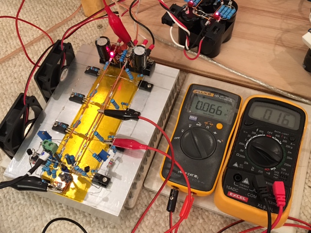
I swapped out two MOSFETs that had high current flow and that fixed the problem. It seems they have a higher inherent current to voltage response. Amp is running at 1.4amps overall now. Individual currents range between 300mA and 370mA ea. Offset is about 15mV to 25mV. Probably because my two JFETs are not thermally couple and floating out in open air where their cooling varies. I could tie them together and put the whole thing closer down next to the input terminal block. That would probably reduce fluctuations.
Attachments
I can't seem to get this from reading the spec sheets. Are the 2SK2014/2SJ313 lateral FETs or vertical FETs? They don't seem to have thermal runaway even though I am doing a poor job of thermal compensation.
I believe they are lateral but what makes them unique is their high transconductance like vertical FET. Basically, lateral with guts !
Nice p2p job ! What's that yellow tape, some sort of insulation tape ?
Eric
Last edited:
That explains why they haven't blown up, it was running almost 2amps but did not run away. That's Kapton tape - yes for insulation so I don't do anything stupid like short the pins to the bare aluminum which is ground. Kapton is actually a good substitute for transistor silicone pads. It can withstand high temps - you can solder on it even.
I think the cult-like status these MOSFETs have is probably due to how linear they are. I have not seen such graphs from another MOSFET. I might have to make an F5 head amp using this now - they like to run at 300mA though so will need bigger power supply and bigger heatsink.
No, they are not lateral.
TO220 lateral is somewhat rare. I only know very few made by the Hitachi/Renesas.
X, consider yourself lucky this fet didn't blow up at 1.1A. The max drain current of both 2SK2013 and 2SJ313 is rated at 1A. This particular one is likely at extreme (low) of the Vgs. A candidate to use it in a HA or preamp.
FWIW, I ran a small GB of these fets. Out of a little over 200 pairs. I found 85% of the 2SK2013 were within 0.2V Vgs; however, the 2SJ313's were all over the places. So, it is definitely worth to spend a little time to measure the Vgs of your remaining stock to best use them.
I guess I was lucky then. Need to be careful with them still. I have another 5 pairs so not much of a choice even if I measured them to match. Maybe buy more?
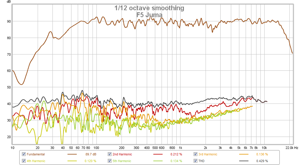
I cranked the volume up on this amp today - it surprised the heck out of me how loud a little amp like this can get and still sound clean. Measurements of my speaker with a mic showed extremely low distortion levels - certainly less than native speaker distortion of -55dB.
I cranked the volume up on this amp today - it surprised the heck out of me how loud a little amp like this can get and still sound clean. Measurements of my speaker with a mic showed extremely low distortion levels - certainly less than native speaker distortion of -55dB.
You can listen to this amp vs others in this virtual audition thread.
http://www.diyaudio.com/forums/soli...audition-very-simple-quasi-mosfet-amp-27.html
The F5 Juma has one of the lowest measured harmonic distortion below 100Hz as measured by a mic from my speakers as compared to 11 other amps. I wonder if it has to do with 4 pairs of outputs waxhnwith own 0.22R source resistor? High damping factor?
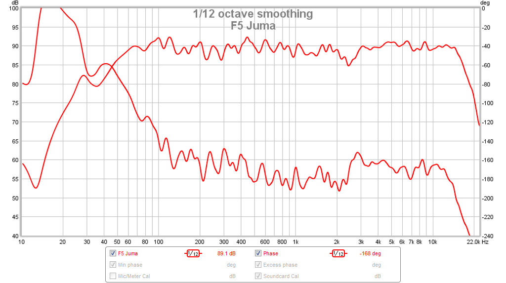
Nice flat phase as measured at speaker:
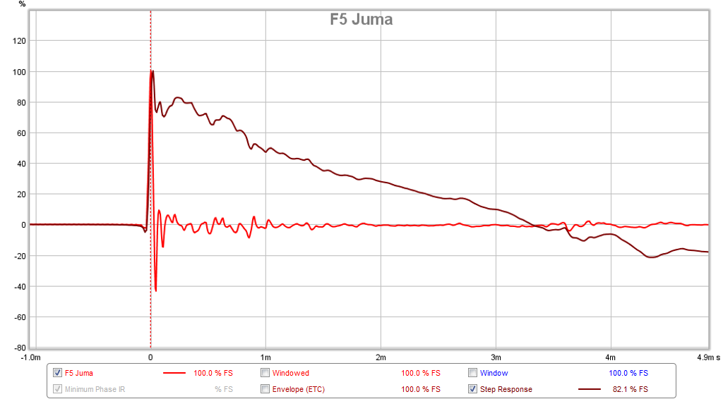
Transient perfect impulse response:
http://www.diyaudio.com/forums/soli...audition-very-simple-quasi-mosfet-amp-27.html
The F5 Juma has one of the lowest measured harmonic distortion below 100Hz as measured by a mic from my speakers as compared to 11 other amps. I wonder if it has to do with 4 pairs of outputs waxhnwith own 0.22R source resistor? High damping factor?
Nice flat phase as measured at speaker:
Transient perfect impulse response:
Hi, I 'd like to build a travel amp as Davide called it, for my 100 db/m speakers. As the ACA shows they are pretty happy with 5 W, so one or two pairs of devices should be sufficient, shouldn't it? Besides that I wonder if it makes sense to lower the rail voltage in this case. Is there a limit one has to respect?
Regards Ernst
Regards Ernst
I think in class A the peak current is about half of bias current. If I did this right it means you need 0.45amps for 5w into 8ohms. These are rated at 1A and should operate probably no more than 500mA ea to be safe. So having two should give you room for peak 500mA into speakers. Rail voltage needs to be maintained so that there is enough room for 6.3v rms. Maybe +/-12v could work?
- Status
- This old topic is closed. If you want to reopen this topic, contact a moderator using the "Report Post" button.
- Home
- Amplifiers
- Pass Labs
- F5 with 2SK2013/2SJ313