Prakit,
there is a way how to further optimize this circuit in order to use it as a preamp.
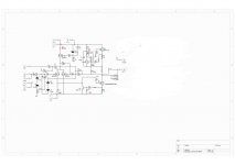
The thing is that feedback resistor are heavily loading the output which is not a problem when driving speakers and using 3 pairs of MOSFETs in output, but for just one pair it's not optimal. In order to raise the value of feedback resistors we have to raise the value of input JFET's source resistors and the only way to do it (and keep the high Id through JFETs) is to introduce appropriate DC bias to JFET's sources. That's what R28 and R29 are for. C4 and C3 are shunting JFET's sources to ground, AC-wise.
R34 and R16 ratio (as well as R35 and R17) is responsible for the ammount of closed loop gain. R23 and R27 are setting the current through output MOSFETs (300mA or higher) and DC offset (the same way as in original F5).
Should be easy to try, and it should sound better. I'd like to hear your impressions...
there is a way how to further optimize this circuit in order to use it as a preamp.
The thing is that feedback resistor are heavily loading the output which is not a problem when driving speakers and using 3 pairs of MOSFETs in output, but for just one pair it's not optimal. In order to raise the value of feedback resistors we have to raise the value of input JFET's source resistors and the only way to do it (and keep the high Id through JFETs) is to introduce appropriate DC bias to JFET's sources. That's what R28 and R29 are for. C4 and C3 are shunting JFET's sources to ground, AC-wise.
R34 and R16 ratio (as well as R35 and R17) is responsible for the ammount of closed loop gain. R23 and R27 are setting the current through output MOSFETs (300mA or higher) and DC offset (the same way as in original F5).
Should be easy to try, and it should sound better. I'd like to hear your impressions...
Attachments
I forgot to mention something about the preamp in post #42 
Using higher value source resistors for input JFETs lowers the OLG, but it's not very important since we need lower CLG in the preamp anyway. I suppose the most will need the gain of about 2V/V so feedback resistors can have lower value than 1k (470R will result in gain about 2.2V/V and it's still high enough resistance that won't overload the preamp).
Using higher value source resistors for input JFETs lowers the OLG, but it's not very important since we need lower CLG in the preamp anyway. I suppose the most will need the gain of about 2V/V so feedback resistors can have lower value than 1k (470R will result in gain about 2.2V/V and it's still high enough resistance that won't overload the preamp).
Well IRF9610 is used in the front end of Aleph 3/30 etc, so they can't be too bad.
But I take your point, the toshiba devices are much more linear according to the data sheets.
Maybe I should also try the toshibas in the front end of my Aleph 30.
/QUOTE]
I bought some of these from Z to test out in similiar setup with Mini-A. Looking for tips assuming they won't drop right in.
Also plan to build this Mini F5 gig with 1 or 2 outputs and see how they do with a pair of lowthers, running off a 12V tranny.
Thanks for sharing.

Juma-
Thanks for the response. I was thinking the 2sk313's as input and CS, and the IRFP240 as CCS and SemiSouth R100 as output. Replacing with one pair of sj74's won't do the heat, but the TO-220's do. I have this running now with the IRFP9610s. Here is a pic. Sorry it is hard to look at. More sorry this is off topic, but I find these Toshiba buggers exciting.
Thanks for the response. I was thinking the 2sk313's as input and CS, and the IRFP240 as CCS and SemiSouth R100 as output. Replacing with one pair of sj74's won't do the heat, but the TO-220's do. I have this running now with the IRFP9610s. Here is a pic. Sorry it is hard to look at. More sorry this is off topic, but I find these Toshiba buggers exciting.
Attachments
If we are talking +/-15V supply optimal version is the one mentioned in post #45. Basically, it's Mini-Aleph-J with k2013 in output section.
j313 as input LTP won't do well with Id=10mA (maybe marginally better than IRF9610, but I doubt it).
IRFP240 and R100 in output will give sub-optimal results with such a low PS voltage.
I see that you are all excited about trying all the new devices at once but don't force it, let the fever cools off
Juma,
1. does this 3 pair of outputs F-5 have more gain than the standard F-5?
2. Is there a thread where all this is laid out?
3. I suppose there are a few other changs besides just adding more mosfets?
russellc
1. 3 pair of what outputs ?
2. What's "all this" ?
3. What's your goal when you ask for "other changes" ?
Please, try to phrase your questions clearly, refer to post numbers and schematics, be precise - I don't know what you think, just what you write...
I got interested in Toshiba's 2SK2013/2SJ313 MOSFETs last year when estman, a forum friend, sent me generously a set of dozen j313s. They impressed me with their superior linearity of transfer characteristics but not until recently (when I got the N-channel complements - k2013) I could not try them in classical push-pull circuit.
Using them in F5 (3 pairs per channel at +/-20V, 400ma per MOSFET for total bias of 1.2A per channel) transformed it into amp that leaves no wishes open.
Schematics and pics are here:
Novi amp sa 2SK2013/2SJ313 - DIYAudio.rs
This is the post I referred to. You said "Using them in F-5 ( 3 pairs per channel...) transforms it into amp that leaves no wishes open."
"All this" refers to the forgoing amp that "leaves no wishes open"
"Other changes" in regards to the F-5 and your adding of the output devices.
Clear enough?
Russellc
Last edited:
Russellc, the post you quoted quoted contains a link to my original thread on DiyAudio.rs where I gave more detailed story but it's in Serbian language and I can't force myself to write the same thing twice. Anyway, you got the point: "leaves no wishes open"...
OK, let me try to answer your questions from post #48:
1. 3 pairs of k2013/j313 give a bit less OLG than 1 pair of IRFP240/9240 but the output stage becomes significantly more linear. CLG is the same. That means that GNFB used is smaller and the end result is better.
2. There are two threads: this one and the aforementioned one at diyaudio.rs
3. Thread at diyaudio.rs contains the complete schematics of the amp and the power supply.
Last edited:
Hi Dennis,
I didn't match them, all of the same polarity were in 5% tolerance and there was a bit less than 10% tolerance between P and N genders.
I suppose that Toshiba's production process is responsible for that - although, the truth is that I had the MOSFETs belonging to same production batch.
By 5% tolerance I mean Id - ranging from 380 to 420mA per MOSFET in situ.
Last edited:
I have to admit that I have not paid much attention to this till this evening.
Indeed, the 2SK2013 / 2SJ313 has a higher (transconductance / capacitance) ratio than, e.g. the 2SK1530 / 2SJ201. The capacitances would be about equal if you replaces 1 2SK1530 (bias 2A) with 6 2SK2013 (each at 330mA), but the transconductance is about 60% higher. And it does operates more into the "linear region".
So congratulations for this clever idea. Pity though that you did not publish any Id vs Vgs curves to show how complementary they are. If I beleive the datasheet, then they are not quite as complementary. But I have to say I have no measurements to prove.
Patrick
Last edited:
... they are not quite as complementary. ...
No, they are not an example of highest level of complementarity, but then again, the F5 topology doesn't care very much about complementarity...
> the F5 topology doesn't care very much about complementarity...
That's your opinion.
Patrick
No, really. It's very easy to compensate for certain level of "uncomplementarity". Adjusting gate stoppers and source degeneration resistors will enable you to optimaly set input JFETs as well as output MOSFETs. NTCs & 5k pots enables fine adjustment of MOSFET's Id. All things considered, perfect complementarity of active devices is not of paramount concern here if you know how to deal with it. Sonic gains fall under the law of diminishing returns.
Anyway, chasing after the perfect curves in active devices is (to some extent) same as with women - if you persist too much with it, you'll miss the essence...
Last edited:
I agree it is not difficult to trim 2nd and 3rd harmonics. Nelson has published a simple trick in his original article.
But if you believe in John Curl (I do) and want to get really low high order harmonics, that is a completely different story.
There are enough Ph.D. thesis published which explain why the human hearing is much more sensitive (on a log scale) to higher harmonics.
We don't have to agree. It is still clever to parallel multiple 2SK2013s / 2SJ313s. Probably not much more expensive.
When I have some time in November, I'll measure a few and see if there is another degeneration trick to get them to become more complementary.
Patrick
Last edited:
Essentially, we agree. The small difference is that there is a certain point of engineering up to which I rely on curves and measurements - from there on the ears take over (I make amps exclusively to listen to the music).
And this is really the first amp that leaves no wishes open for me - in every sense of that phrase (physical and electrical design/dimensions as well as the music reproduction)
And this is really the first amp that leaves no wishes open for me - in every sense of that phrase (physical and electrical design/dimensions as well as the music reproduction)
- Status
- This old topic is closed. If you want to reopen this topic, contact a moderator using the "Report Post" button.
- Home
- Amplifiers
- Pass Labs
- F5 with 2SK2013/2SJ313