or look at this way
lets say we have two amps, A and B
amp B is special, and 'might' be 2% better than amp A
but only when built by an expert
or used under 'certain conditions'
means 99% of all builders will still achieve better result with amp A
or in worst case
how good is the best amp if its gone in a month
lets say we have two amps, A and B
amp B is special, and 'might' be 2% better than amp A
but only when built by an expert
or used under 'certain conditions'
means 99% of all builders will still achieve better result with amp A
or in worst case
how good is the best amp if its gone in a month
No, you are not - but you might get yourself into one...Then I'm in trouble
Go ahead with lower PSU voltage and higher/lower bias, just leave the biasing scheme alone (don't omit the pots, NTCs, etc...). Read carefully the F5 service manual and understand the temperature/DC offset dependency i.e. how MOSFETs work and amp as a whole.
Joggling with things you don't completely understand can leave you with burned amp, speakers, house...
Zero tempco is not guaranteed at 0.6A - it's just written in the datasheet (which may not be absolutely true for all devices - some experimenting and measuring is always needed).
Last edited:
Experimenting and measuring is my day-time profession so this is indeed also where I planned to start with this version of the "F5J".Joggling with things you don't completely understand can leave you with burned amp, speakers, house...
Zero tempco is not guaranteed at 0.6A - it's just written in the datasheet (which may not be absolutely true for all devices - some experimenting and measuring is always needed).
I have been tracing a few thousand FETs over the last year or so and having a good (experimental) look at the zero tempco point can only increase my understanding of these devices.
Thanks for the help and encouragement
Nic
Experimenting and measuring is my day-time profession ....
Then you know how cruel reality can be
I'm sure you'll be presenting us new insights

Not much insight - just some dataI'm sure you'll be presenting us new insights
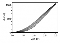
I slow-fried a 2SK2013 and recorded traces every 6 degrees of temperature rise.
0.6A does not look particularly special to me - in fact 1.1A seems more like the right drain current for zero tempco, but unfortunately beyond the device rating
The measurements are not really the same as data sheet......
The zero tempco occurs at the correct Vgs (about 3V), but I measure higher current
Could the difference in Vds (15V vs. 10V in data sheet) explain this?
Attachments
NicMac, that's what I was talking about - not all 2sk2013s are born equal. The one batch I got was in compliance with datasheet, the other one was not (zero tempco was in 800-900mA area).
That's why it's good to leave the NTCs and pots in the circuit.
OTOH, that picture of yours shows a rise of Id of about 170mA at Vgs=2.5v for a temperature change of 50 degrees Cels. and that's not a big deal anyway...
Bias it at about 450mA (cold) and the bias will rise to about 600mA when hot, and everything's OK.
Last edited:
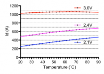
I have attached the data plotted in a different way to better illustrate how current change with temperature for selected values of Vgs. Black dots are the measured values and curves are quadratic fits.
I will have 3 different batches of 2013/313 to look at so maybe I will find some with lower zero tempco. I'm not really counting on this as the increase in current is indeed fairly limited and unlikely to cause thermal runaway. It will work just fine (even without NTC).
Also I have no intention of matching FETs for three parameters
Cheers,
Nic
Attachments
...the increase in current is indeed fairly limited and unlikely to cause thermal runaway. It will work just fine (even without NTC)....
Of course. Just make sure to use decent heatsink that will keep the Tj below 100 degrees Cels. and everything will be fine.
Power Supply Questions
Hello,
I plan to build this Amp, as outlined in Juma's first post. I just ordered 20 pair of the 2SJ313/013 from Prakit, so I will soon have some matching to do. I will be making a slight variation, so have a few questions.
1) I already have 2 Vicor FlatPac switching supplies, which I would like to use. I plan on building the power supply section in a separate box from the main amp. The supplies are 24V, but can be trimmed down to 20V. Obviously one would be used for the (+) and the other for (-) sides. They are not matched, but are from the same series. One is rated at for 8.3A and the other is 6.25A. Will the 6.25A be enough, or it important that they both be the 8.3A model?
http://cdn.vicorpower.com/documents/datasheets/ds_flatpac.pdf
2) I plan on using an LC filter on the power supply outputs. Page 30 of the link below recommends 200nH. I found this Digikey #732-2146-1-ND which looks comparable. The datasheet recommends tantalum caps. But is that critical? No electrolytics? Opinions on the LC filter in general?
http://cdn.vicorpower.com/documents/applications_manual/DesignGuideAppsManual_200J00.pdf
3) Over on swap meet, Tony399 is selling a stash of 2SK170/74s. What Vds/Idss do I need? He will match. I'm sure this info is somewhere, but I can't find it.
4) I realize that the PCB's that Georg made are all gone. Anyone else interested in a set? Maybe if the requests go up, he can make another run?
Thanks!

Monty Python - Naked Organist - YouTube The flute is there somewhere too.
Scots are all a bunch of perverts, who else thinks up names like 'kcoC rehtaeW', or 'Songs of the Woody'.
(and they're thick as a brick as well)
Scots are all a bunch of perverts, who else thinks up names like 'kcoC rehtaeW', or 'Songs of the Woody'.
(and they're thick as a brick as well)
Last edited:
Don't you really know what Thick as a Brick is?
Oh boys! You must be very young.
Jethro Tull - Thick as a Brick full - YouTube
One of the most famous song when we were young
Oh boys! You must be very young.
Jethro Tull - Thick as a Brick full - YouTube
One of the most famous song when we were young
Don't you really know what Thick as a Brick is?
Oh boys! You must be very young.
Jethro Tull - Thick as a Brick full - YouTube
One of the most famous song when we were young
THANKS!!
- Status
- This old topic is closed. If you want to reopen this topic, contact a moderator using the "Report Post" button.
- Home
- Amplifiers
- Pass Labs
- F5 with 2SK2013/2SJ313