jacco,
I'll have to look back through my search history cause I did see a 1 mil 12" X 12" sheet somewhere - not mica but a Kapton/alternative product.
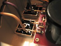
However, you did point out something I have been considering and planned to ask about at some point. I don't know if a careful butt joint of something like one of the following two products would jeopardize the dielectric seal at the joint. That would not be a problem between faces like the earlier picture points to, as no electricity exists at that level. But generally, I'm curious if anyone has made (or even considered) a successful insulator splice for a power transistor.
Also, as a discrete nubee, does anyone make an insulated PT (as available with LM3886 chips) where only heat transfer compound is needed?
1 Mil Kapton Tape - 3in, Polyimide Tape Online
Kapton Film (HN Series) - 2in, Polyimide Tape Online
I'll have to look back through my search history cause I did see a 1 mil 12" X 12" sheet somewhere - not mica but a Kapton/alternative product.
However, you did point out something I have been considering and planned to ask about at some point. I don't know if a careful butt joint of something like one of the following two products would jeopardize the dielectric seal at the joint. That would not be a problem between faces like the earlier picture points to, as no electricity exists at that level. But generally, I'm curious if anyone has made (or even considered) a successful insulator splice for a power transistor.
Also, as a discrete nubee, does anyone make an insulated PT (as available with LM3886 chips) where only heat transfer compound is needed?
1 Mil Kapton Tape - 3in, Polyimide Tape Online
Kapton Film (HN Series) - 2in, Polyimide Tape Online
Depends on the insulator thickness, no ?
Diamonds are a fool's best friend : http://www.diyaudio.com/forums/solid-state/31077-krell-ksa-50-pcb-99.html#post777532
(worst case, one could glue the gap shut, i'd think)
Diamonds are a fool's best friend : http://www.diyaudio.com/forums/solid-state/31077-krell-ksa-50-pcb-99.html#post777532
(worst case, one could glue the gap shut, i'd think)
Last edited:
Well, Well! 
I actually have 12 of the Thermalloy pads for my discrete amp, but I haven't used them as I thought I'd screwed up my online order. Was also under the impression the thickness would inhibit heat transfer. Are those in the link clean or did you add a compound?
I actually have 12 of the Thermalloy pads for my discrete amp, but I haven't used them as I thought I'd screwed up my online order. Was also under the impression the thickness would inhibit heat transfer. Are those in the link clean or did you add a compound?
Attachments
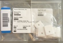
They require goop.
As shown in Patrick's article, thermal conductivity of Aluminum Oxyde is really good, but the insulator thickness seriously drops that advantage.
Back in the mid '80s I bought 4.5mm AlOx insulators, pretty useless compared to mica.
Advantage then was that they could be used over and over again, big plus if one hasn't finished a project and already coming up with the next. (as neat as braided hose with fast connectors, to someone into boats and cars)
In time, they became thinner, the Aavid ThermAlloys of the Krell thread do better than mica, also better than e.g. trendy Bergquist ceramics filled sheet items at the time.
They are passing 10sec hand touch test with 0.6A/device bias. That was maximum possible for these heatsinks. But here now daytime temperature is 30deg Celcius. It will touch 40-45 during next couple of months. So keeping in mind that rise, I reduced bias to 0.55A/device.
Speaker grounds are taken from amp PCB. From PS ground(floating), wires go to earth ground isolator and amp board.
Ah, I get it... your T-ambient is a bit different than in the Netherlands
Here it's about +5 deg Celsius outside, and in my room 18 deg Celsius, hahaha
Maybe I have to reconsider to take my speaker grounds from the amp-board, instead of my PSU-board...
Thanks!
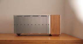
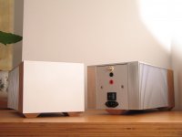
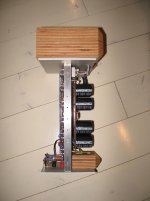
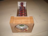
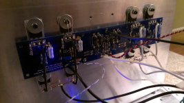
Here are some photos of my finished F5 turbo monos.
Each Mosfet is biased to 0.8A.
The bases are 59°C, the heatsinks are 57°C.
The room temperature is 25°C.
Each Mosfet is biased to 0.8A.
The bases are 59°C, the heatsinks are 57°C.
The room temperature is 25°C.
Attachments
Here are some photos of my finished F5 turbo monos.
Nice work, love your design!
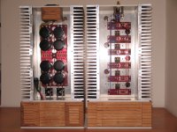
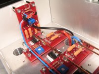
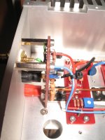
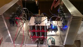
Here is a pic of my F5c with parallel source diodes. Im doing a preliminary bias now, its at .85 amps per device. Im trying to dial in on where the diodes begin conducting. It has .47 ohm source Rs, and 100 ohm parallel feedback Rs.
I dont think I can bias this much higher on my horizontal heatsinks.
The psu is all C right now, im waiting for choke coils.
I dont think I can bias this much higher on my horizontal heatsinks.
The psu is all C right now, im waiting for choke coils.
Attachments
Here are some photos of my finished F5 turbo monos.
Each Mosfet is biased to 0.8A.
The bases are 59°C, the heatsinks are 57°C.
The room temperature is 25°C.
Wow, those are ridiculously awesome in so many ways! I may steal some of your design ideas for my next build.
Here are some photos of my finished F5 turbo monos.
Each Mosfet is biased to 0.8A.
The bases are 59°C, the heatsinks are 57°C.
The room temperature is 25°C.
Nice cable management! And I am glad you included the side shot otherwise I would not have understood what was happening there. I like how you nested the transformer in the back like that and flipped the cap bank under the rest of the components.
It unfortunately gives me ideas now...
Here are some photos of my finished F5 turbo monos.
Each Mosfet is biased to 0.8A.
The bases are 59°C, the heatsinks are 57°C.
The room temperature is 25°C.
Wow real nice

Turn your sinks the other way. It has a great effect on dissipation. I wouldn't go much higher than .450 across Rs and that's assuming easy load.
The horizontal sinks were a design consideration based on some other materials I had. I had a se burning amp in the chassis, but couldn't get the bias I wanted. The f5c is working out well though, at .4 volts across .47R. Any higher, and it's a little hot.

Wow, those are ridiculously awesome in so many ways! I may steal some of your design ideas for my next build.
Thank you all.
Please feel free to use it.
Many thanks to Papa for the fantastic design.
- Home
- Amplifiers
- Pass Labs
- Pictures of your diy Pass amplifier