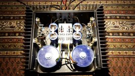
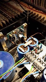
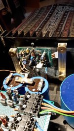
I inserted my BTSB Buffer with 6dB additional gain between the Iron Pre and the BOO Amp. More useable volume range now. 

you can insert additional repeater as autoformer in between Iron Pre and follower amp
maybe you'll like it, maybe not ....... it'll result in some color
Edcor, Jensen, Cinemag - if you have a pair handy
maybe you'll like it, maybe not ....... it'll result in some color
Edcor, Jensen, Cinemag - if you have a pair handy
Indeed, that an interesting option, thanks. Transformer gain is one thing I’ve yet to play with (other than the stock VFET SE input). I do not have any handy. 
I just heard something new in a song I hadn’t noticed before. So I guess all is going well. Extra layering of ancillary instruments in a track of The Good, the Bad, and the Queen. I am thrilled by such experiences.

I just heard something new in a song I hadn’t noticed before. So I guess all is going well. Extra layering of ancillary instruments in a track of The Good, the Bad, and the Queen. I am thrilled by such experiences.
Attachments
Last edited:
Transformer gain is one thing I’ve yet to play with
I believe there is some of that in Iron Pre

At my place when those kinds of things happen it ends like thisI just heard something new in a song I hadn’t noticed before. So I guess all is going well.
And lately it happens very often 🙂
It took me so long to get this done that Gianluca changed the heatsink rails at Modushop in the time since I started with this amp. My heat spreaders no longer fit, so I improvised with spacers. The chassis is now is a Tie-Fighter.
You might consider a nice anodized aluminum strip from McMaster-Carr to fill that gap.
https://www.mcmaster.com/products/a...d-multipurpose-6061-aluminum-sheets-and-bars/
Nice to hear someone else is building during the summer months!
I kinda like the gap. 
I could always swap rails with one of my older Modushop chassis… But that’s gonna have to wait until I’m done living with this splendid amplifier in the main system.
The newest amp is always the best!

I could always swap rails with one of my older Modushop chassis… But that’s gonna have to wait until I’m done living with this splendid amplifier in the main system.
The newest amp is always the best!

Project Heat Sink Rail Swap is complete! As threatened, I swapped the older style rails from another chassis (my TDV) with the newer window frame rails in my recent Boo OS build. A theoretically simple* mechanical task took all damn night.  Too late for listening tests, so I’ll do that tomorrow.
 Too late for listening tests, so I’ll do that tomorrow.
Attachments
Looks so great!
It would be cool if you could post the schematics (or block diagram) of your psu solution (or maybe you already have it somewhere? and I overlooked it), I like the combo SMPS-CRC-L-something.
It would be cool if you could post the schematics (or block diagram) of your psu solution (or maybe you already have it somewhere? and I overlooked it), I like the combo SMPS-CRC-L-something.
My external dual mono linear supply in the main system is described here. Whatever amp it powers has an extra cap bank in the amp chassis. So this is +/-24VDC CLCRC.
I also have an enclosed MicroAudio SMPS500CLA I use for testing (also +/-24VDC).
My TDV is dual mono Meanwell RPS-200-27C plus DiyAudio Store power supply cap banks. The chokes are part of the amp circuit.
I also have an enclosed MicroAudio SMPS500CLA I use for testing (also +/-24VDC).
My TDV is dual mono Meanwell RPS-200-27C plus DiyAudio Store power supply cap banks. The chokes are part of the amp circuit.
A theoretically simple* mechanical task took all damn night.Too late for listening tests, so I’ll do that tomorrow.
Hilarious. And the same thing happens to me with pretty much any project around the house... 😛
Still going strong after 20 years I discovered pass labs amplifiers .
This is an aleph 5 ,the Mark Finiss version I just finished yesterday.
Back in 2004 he published his efforts of building alephs.
I followed his instructions and it was an instant success.
Thanks to him and of course more importantly the generous contribution of Papa (nelson pass) I enjoy the amazing sounds of his designs.
Greetings from Greece to all !
Just finished a new build of an H2 V2 preamp with bluetooth. Let's start with a couple of pix of the innards:


The volume knob was the trickiest part to engineer, because I wanted it to 1) have an illuminated indicator, and 2) have no visible hole for the set screw. So I made it in two parts. The base plate has two copper tracks (12 ga. wire embedded in the plexiglass) which contact two spring-loaded pins in the amp faceplate. Two cylindrical magnets both register the wood knob to the base plate and also mate to two similar magnets in the knob. Hopefully the pix explain it better than I can:


The front, finished:

...and the back:

I built this preamp as a birthday gift for my daughter. I'm also giving her my old ACA monoblocks, and I'll be building her a pair of speakers to complete the system.
Here it is with the monoblocks:

Cheers! 🍺
The volume knob was the trickiest part to engineer, because I wanted it to 1) have an illuminated indicator, and 2) have no visible hole for the set screw. So I made it in two parts. The base plate has two copper tracks (12 ga. wire embedded in the plexiglass) which contact two spring-loaded pins in the amp faceplate. Two cylindrical magnets both register the wood knob to the base plate and also mate to two similar magnets in the knob. Hopefully the pix explain it better than I can:
The front, finished:
...and the back:
I built this preamp as a birthday gift for my daughter. I'm also giving her my old ACA monoblocks, and I'll be building her a pair of speakers to complete the system.
Here it is with the monoblocks:
Cheers! 🍺
Very fancy! I hope your daughter appreciates it.
More details of the volume LED connection, please. What did you use for the pins that contact the circular traces? And I do not 100% understand what you mean by 'cylindrical magnets'. The magnets have to match/find/be opposite to something to attract to regardless of the volume pot position. So, is there a steel disk opposite the magnets, or are the magnets actually ring magnets surrounding the volume potentiometer axis, or something else?
More details of the volume LED connection, please. What did you use for the pins that contact the circular traces? And I do not 100% understand what you mean by 'cylindrical magnets'. The magnets have to match/find/be opposite to something to attract to regardless of the volume pot position. So, is there a steel disk opposite the magnets, or are the magnets actually ring magnets surrounding the volume potentiometer axis, or something else?
The magnets fit into two holes in the knob "cap", which also have magnets inset into them. This keeps the cap in place and correctly registered to the LED, but also allows it to be removed with a gentle tug. Perhaps another pic will make it clear:

As to the contact pins, I'll have to draw a picture. BRB...
As to the contact pins, I'll have to draw a picture. BRB...
Here's a sketch of (one of) the contact pins... I used little brass brads (maybe sold as escutcheon pins... I don't recall). The brass follower I turned down from a brass screw, using a drill press and a file. The LED power wire is soldered to the follower. Two of these assemblies are contained in the wood housing, which is attached to the faceplate with a screw. You can see the wood housing in the (not very good) detail pic...


- Home
- Amplifiers
- Pass Labs
- Pictures of your diy Pass amplifier

 Ha! Of course. The little critters are popping up all over.


