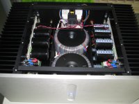
Finished F5T v3
Finally finished the v3.
It's exactly build according the Nelson Pass circuit except for the (better?) Toshiba MOSFETs in the output stage.
In the version 2, I biased the MOSFETs at 1,25 A @ 32V, which resulted in very hot MOSFETs. Around 70 degrees Celsius.
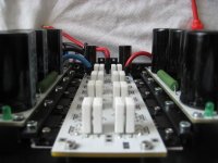
Now I've doubled the output devices, so half the current for each device, and used Kerafol instead of mica and goop. Also clamped the output MOSFET's and yes, now I have only 5 a 6 Celsius difference between the heatsinks and the output devices.
Kerafol 86/82 under big pressure rocks !
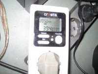
Heatsinks max out around 58 C with 0,225A per rail bias and the MOSFETs are around 62 C.
Can't use 2.5 A bias per rail since my T ambient is around 25C this time of year
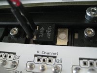
I also implemented a thermal protection by glueing 75C switches on the Toshibas.
Didn't need too implement C3 and C4 for stability.
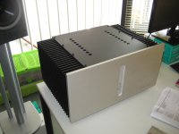
The amp is dead silent, and it sounds so great !
During the rebuild to a version 3, I constantly listened to my standard F5 ( which isn't bad!) but this v3 has definitely more body, bigger soundstage, more bass and sounds a bit more detailed and relaxed, yes.
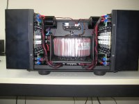
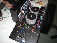
Attached are my last pictures for this project.
Now it's time to build a set of high end speakers... suggestions are welcome...
Although I already ordered the ACA PCB's and the beautiful red chassis for a little desktop computer class A Amp ( or maybe for my son) , I must say the Aleph J pre-order PCB's in the store are tempting
Would like to hear how a single ended class A will sound
Walter
Finally finished the v3.
It's exactly build according the Nelson Pass circuit except for the (better?) Toshiba MOSFETs in the output stage.
In the version 2, I biased the MOSFETs at 1,25 A @ 32V, which resulted in very hot MOSFETs. Around 70 degrees Celsius.
Now I've doubled the output devices, so half the current for each device, and used Kerafol instead of mica and goop. Also clamped the output MOSFET's and yes, now I have only 5 a 6 Celsius difference between the heatsinks and the output devices.
Kerafol 86/82 under big pressure rocks !
Heatsinks max out around 58 C with 0,225A per rail bias and the MOSFETs are around 62 C.
Can't use 2.5 A bias per rail since my T ambient is around 25C this time of year
I also implemented a thermal protection by glueing 75C switches on the Toshibas.
Didn't need too implement C3 and C4 for stability.
The amp is dead silent, and it sounds so great !
During the rebuild to a version 3, I constantly listened to my standard F5 ( which isn't bad!) but this v3 has definitely more body, bigger soundstage, more bass and sounds a bit more detailed and relaxed, yes.
Attached are my last pictures for this project.
Now it's time to build a set of high end speakers... suggestions are welcome...
Although I already ordered the ACA PCB's and the beautiful red chassis for a little desktop computer class A Amp ( or maybe for my son) , I must say the Aleph J pre-order PCB's in the store are tempting
Would like to hear how a single ended class A will sound
Walter
Attachments
-
 Thermally coupled JFETs.jpg412.7 KB · Views: 1,771
 -
 4 output on Kerafol.jpg415.1 KB · Views: 1,008
 -
 Very nice inside view.jpg348.2 KB · Views: 1,145
 -
 Open chassis.jpg374.9 KB · Views: 1,589
 -
 Thermal protection.jpg394.2 KB · Views: 1,604
 -
 Turbo-engine V3.jpg295.7 KB · Views: 1,655
 -
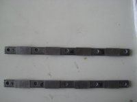 Clamping bars for the MOSFETs.jpg171.8 KB · Views: 1,670
 -
 Inside with frontpanel.jpg316.7 KB · Views: 1,033
 -
 Ooh, my God....jpg262.9 KB · Views: 934
 -
 finally ready.jpg251.8 KB · Views: 984
Now it's time to build a set of high end speakers... suggestions are welcome...
One of the Jenzens from Troels Gravesen. I heard the Jenzen ER: it's magnificent. I am currently building the Jenzen NEXT and if you wish there are even Higher End Jenzens
Thanks! Those cabinets are difficult to build...for me, a starter...only built a quite big subwoofer so far...
Finally finished the v3.
It's exactly build according the Nelson Pass circuit except for the (better?)
Walter

 very good, nice to see a completed unit. Especially using teabags boards. Hopefully your build along with others, will help people like me along their path of building something similar.
Thanks, yes I ordered two and they work fine! Temperature protection and softstart with a small switch possible.That is nice. I noticed you have an ebay soft start module. Does that one work well?
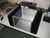
Very nice where the chassis come from ?
I build it myself, see picture and earlier posts. The nice frontpanel is from Hifi2000.it
Thanks, that's why I post so many pictures, hoping I can inspire and help others with their builds...
Walter
Attachments
Nice one Walter.
I will have exactly the same built using the Teabag boards and the Toshiba MOSFETs, also 4 pairs per channel.
What were the values of the resistors that you used, as well as the trafo specs?
I have used Panasonic T-HA 27000mF 50V caps in my Teabag PSU boards. My case will be built by me in exactly the same manner as my KSA50 clone.
Bob they are available to back order in the store.
Thanks. I have been considering those. I've also investigated the simple Kapton film as a lower cost alternative. Has anyone experimented with that product?
Nice one Walter.
I will have exactly the same built using the Teabag boards and the Toshiba MOSFETs, also 4 pairs per channel.
What were the values of the resistors that you used, as well as the trafo specs?
I have used Panasonic T-HA 27000mF 50V caps in my Teabag PSU boards. My case will be built by me in exactly the same manner as my KSA50 clone.
Thanks, which resistors are you referring to?
The source resistors are 0.47 Ohm 5W Fukushima Futaba MPC74's which parallels to 0.235 Ohm 10 Watt
Other resistors in the signal path are Dale CMF55's.
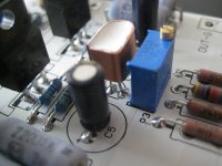
Notice that I lowered R5 and R6 from the original design from 1K to 475Ohm for better biasing the Toshibas.
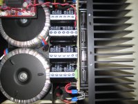
The trafo spec: Amplimo 2 x 625VA 2x25V 2x 12.5 Amp.
So total of 1.25KVA for two channels.
Looking forward to see pictures of your build!
Walter
Can you give some info on the source and cost of the Kerafol you used. Love the tight compact component placements
Bob, I ordered them in Europe :
Warmtegeleidende folie Keratherm - Rood 86/82 Kerafol 86/82 (l x b) 100 mm x 100 mm Dikte 0,25 mm 6.5 W/mK in de Conrad online shop
So around 20 dollar for 100 x100 mm.
Don't know if they ship to the USA...
I cut them with a very sharp scalpel blade.
Zhoufang was selling Keratherm pads for $1 each + shipping. $20 minimum order. They look large enough to cut in half for many uses.
http://www.diyaudio.com/forums/vend...therm-red-86-83-isolators-247-1-ea-stock.html
http://www.diyaudio.com/forums/vend...therm-red-86-83-isolators-247-1-ea-stock.html
Zhoufang was selling Keratherm pads for $1 each + shipping. $20 minimum order. They look large enough to cut in half for many uses.
http://www.diyaudio.com/forums/vend...therm-red-86-83-isolators-247-1-ea-stock.html
PM sent. Hope that deal is still active.
Google doesn't do a "translate" pop-up on the German site. Maybe someone who speaks the language will check out sales to the U.S. and post that information.
Last edited:
- Home
- Amplifiers
- Pass Labs
- Pictures of your diy Pass amplifier