My first step into the world of Nelson Pass amplifiers.
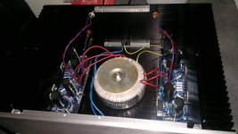
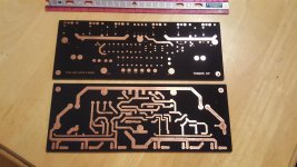
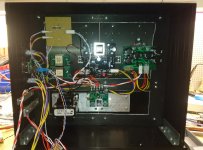
I made my own PCB with F5, capacitors, rectifiers and fuses. All in one.
The last days I built up and switched on. I am very impressed with the quality of the F5.
My first pass amplifier, but certainly not my last one.
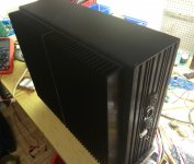
Next comes the case.
I made my own PCB with F5, capacitors, rectifiers and fuses. All in one.
The last days I built up and switched on. I am very impressed with the quality of the F5.
My first pass amplifier, but certainly not my last one.
Next comes the case.
An externally hosted image should be here but it was not working when we last tested it.
An externally hosted image should be here but it was not working when we last tested it.
An externally hosted image should be here but it was not working when we last tested it.
Wow! Meticulous work and top notch photography!
I agree about less then ideal placement of FETs but I don't think you'll have a problem there. You might have a problem with bridge rectifiers. In my (stereo) F5s they are the 2nd hottest component (after the inrush NTC) and I have them mounted on a separate heatsink.
However, you built mono-blocks so your rectifiers pass only 1/2 of total current - maybe you can get away with it without the heatsinks. I would consider them in any case, at least to pull the heat away from the PCB.
Beautiful work, keep it going!
It's no big deal about the Mosfets. The Mosfets can also be mounted vertically on the PCB. And then mount the PCB crosswise to the heat sink.
I had this big used heatsink, it works so well. I have about. 42... 43°C Heatsink temperature.
The rectifiers remain under the data sheet specifications, but it is also possible to mount them under the PCB and place them directly on the heat sink. Of course, cooler is always better.
@labjr:
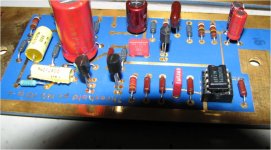
The red Wima capacitors are parallel to the large capacitors. The one in the middle is for the line in - that's optional, I don't know typical for a pass amplifier. On the one hand I don't know if my preamplifier is DC free, on the other hand I wanted to provide the space on the board, a wire jumper can always be set.
Thank you for the positive answers.
I had this big used heatsink, it works so well. I have about. 42... 43°C Heatsink temperature.
The rectifiers remain under the data sheet specifications, but it is also possible to mount them under the PCB and place them directly on the heat sink. Of course, cooler is always better.
@labjr:
The red Wima capacitors are parallel to the large capacitors. The one in the middle is for the line in - that's optional, I don't know typical for a pass amplifier. On the one hand I don't know if my preamplifier is DC free, on the other hand I wanted to provide the space on the board, a wire jumper can always be set.
Thank you for the positive answers.
Pass Labs Aleph 5 clone, Pass Labs preamp p1.7 clone with attenuator separate transformers for each channel and signal, and 192bit/24khz dac all diy paired with JBL L90 with upgraded crossovers cables audioquestmidnight also high end pioneer S-W1EX subwoofer. The first picture is of the upgraded crossover I'm searching for a picture of original to compare so if somebody has JBL L90 and is willing to open the woofer and take a picture i would be very grateful also planning to make a diy dd66000 with drivers from 4435 cheers
https://www.pioneerelectronics.com/PUSA/Home/Speakers/Subwoofers/S-W1EX
https://imgur.com/a/IgQhu
sistem - Album on Imgur
Imgur: The most awesome images on the Internet
Imgur: The most awesome images on the Internet
https://images2.imgbox.com/b4/52/0OkG6ekq_o.jpg
https://images2.imgbox.com/a2/d3/CGnVVisZ_o.jpg
http://imgbox.com/95vR463X
https://images2.imgbox.com/c5/b2/gKz63w21_o.jpg
https://www.youtube.com/watch?v=Lh_7R6qIy6I&t=178s
tannoy 605 with aleph
https://www.youtube.com/watch?v=zWas7l3A9SY
jbl l90 with aleph and upgraded marantz cd40 upgrade includes lamps acoustically treated room all walls covered with plush curtains and carpets on the floor 2:35 perfect sound too bad the camera was bad quality audio recording and almost none bass phone samsung s3
Last edited:
another Aleph 5 coming up
Another Aleph 5 coming up - definitely next year at this rate.
Why an Aleph 5? Why such an old hunk of crap ?
?
Until I try the M2, I contend Alephs are the best to my ears on my Klipshchhe Fortes and Fortes are the best to my ears in a long time.
edit: and these things have no business sounding so good, using the same devices you'd probably find in an elevator motor controller or something.
I'm gutting my KSA Klone chassis. It just won't do.
Made some roomy boards.
Another Aleph 5 coming up - definitely next year at this rate.
Why an Aleph 5? Why such an old hunk of crap
?Until I try the M2, I contend Alephs are the best to my ears on my Klipshchhe Fortes and Fortes are the best to my ears in a long time.
edit: and these things have no business sounding so good, using the same devices you'd probably find in an elevator motor controller or something.
I'm gutting my KSA Klone chassis. It just won't do.
Made some roomy boards.
Attachments
Last edited:
Nice looking boards, @mpmarino.
thanks JY. I would love to have a gold plating facility. I love the look of the old Threshold boards. So roomy and luxurious
Attachments
JAJAJA Tim
Tim de paravicini, Tell us, how sound it? No better than FW....
Joking of course .....
EAR 859 - interesting sounding ...... sound is pretty direct in your face , pretty open
somewhat lesser in bass department , comparing to what I'm used with FW ........ but I heard it just shortly , so ....
all in all - good amp ........ different , but not better nor worse
EAR 859 - interesting sounding ...... sound is pretty direct in your face , pretty open
somewhat lesser in bass department , comparing to what I'm used with FW ........ but I heard it just shortly , so ....
all in all - good amp ........ different , but not better nor worse
Jama my friend, is a fanatic of FW, now is listening SE with 45 tubes, at the first time when he finished the first prototype he measured in some, square wave, he showed me sawtooth wave completely disappointed, I said, try to measure it right now, since this moment he became a fan of VT, I started with VT and now I am following NP,
At last it is almost finished.
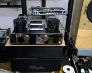
The top is a current source F6 and the bottom is an inductor CCS Zen amp. So two nice current source amps but a bit more power in the F6 for the woofers. The amount of heat sinks is probably extreme overkill but it works
The power supplies are external power bricks.
The top is a current source F6 and the bottom is an inductor CCS Zen amp. So two nice current source amps but a bit more power in the F6 for the woofers. The amount of heat sinks is probably extreme overkill but it works
The power supplies are external power bricks.
Attachments
- Home
- Amplifiers
- Pass Labs
- Pictures of your diy Pass amplifier