I wouldn't say that!
When I saw this, I thought f*?%, that looks dangerous!
PLEASE make it safe, you only get one life, it's not a game, it doesn't reset if you loose.
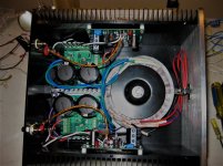
SIMPLE TRICK when dealing with mains wiring, if you don't have a proper PCB to mount the components and fasten wiring to, use a clean dry piece of wood screwed to the chassis, screw a length of insulated terminal block on top, and use every other terminal for connections to provide adequate insulation, also ancor the wire at the connection, you don't want it shorting out to something if the connection brakes.
The CL60's get hot in use, bend the CL60's to a vertical position - away from the wood, it's also the best orientation for cooling.
Talking of shorting out, the blue wire dissapearing into the chassis - DO NOT DO THIS, its carrying mains voltage; vibration could cut through the insulation, you don't want that to happen; and it's also good practice to twist the mains & transformer primary and secondary wire pairs together, don't over do it, one complete twist per 3cm is more than adequate, then give the wires a second coat of insulation, heatshrink is ideal (I use it unshrunk - if it shrinks, theres a heat problem), spiral wrap insulation or nylon braid can be used, it's better tha nothing.
For a first time builder with no experiance, I take my hat of to you sir.
I want to add that those "Euro-Block" connectors are dangerous with stranded wire unless you put a crimp end on the wire. I used them in my Aleph J and it arced, burning the terminal strip. Fortunately it arced to open rather than to ground and didn't start a fire. The terminals were nearly burned/melted into contact with the chassis. I recommend the barrier strip type of terminal blocks with crimp terminals and insulation to prevent accidental contact with mains voltage or at least a crimp cap on stranded wire if you must use those terminal blocks.
Use ferrules on multistranded wire when using the euro style terminal strip
For the wire through holes you can drill out the hole to a larger diameter and insert a rubber grommet to protect the insulation from damage.
Well, live and learn. One year ago I didn't know what a capacitor was and did. Not that I know much more now, but I'm enjoying the process of learning quite a lot. I will make everything as safe as possible following those recommendations. In fact, I was pretty unsure of that part, but it seemed to be right to me. The mains through the holes were... tight to say the least, and I was surprised that I saw that in other constructions, that's why I did it so.
Please, first time DIYers, follow the "wise guys advises" and beware of amateurs like me. We post photos not to show the right way, but to be corrected.
Thank you very much everyone.
Well, many of us Europeans get on fine with the "Euro-Block" connectors.
They do benefit from being anchored, but dabenza has done that with wire-ties. All good in my book.
Good advice on the wires-through-holes, though. Grommets (or re-routing) are in order here. And I'd also bend the thermistors vertical.
Just my take on it all.
Cheers,
Jeff.
(FWIW, EU electrical codes require RCDs/GFCIs pretty much everywhere while the American NEC only requires them in wet locations.)
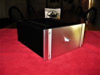
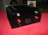
Finished today. 10/07/2017. ACA, Linear PS.
Nice work! I am using same case for Silicon Harmony, another SE Class A design but with SMPS and cap multiplier.

I finished my F5 Turbo v3 monoblocks two years ago, my build thread is here;
(Aloha F5 v3 Monoblock build), but I never posted final picks here.
About a year and a half ago we moved to a house in Kahala with jalousie windows and only a few window A/C units. Since these amps put out so much heat I have been using my KT150 tube monoblock amps. Pulled out the F5's today and realized I missed the energy of these amps.
Decided to build an old fashion (modernized) console and incorporate these F5's into them, with different heatsinks and new chassis's. So figured I post some pics before the "remodel"!
Where is a good place to detail my console build? Mahalo!


Nice work! I am using same case for Silicon Harmony, another SE Class A design but with SMPS and cap multiplier.
Really nice case
Beautiful F5T build congratulations
Do your schassis get some opening for better hot air flow ?
Thanks for the compliment!
I have a fan pushing into the case and existing around the blank plates, top, bottom, middle to indirectly move air around the heatsinks.
In the new console I will be adding heatsink capacity.
In your signature you mention full range speakers. I'm building the console in a way that I can change drivers/front baffle to see what sounds best. First up is a pair of rebuilt JBL LE8T's including magnets recharged by Orange County Speaker. I've had them a couple years but never opens the box till today. I had build some cabinets for them back then too, put them together today and been playing them most of the day. Takes a 100 or so hours to get them listenable, but not bad right now.
The F5's are definitely overkill.
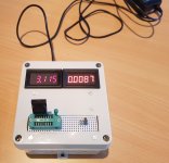
Pass FET tester
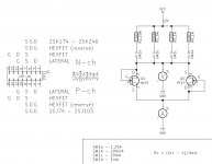
Together with a friend I recently built a FET tester based on Pass' articles.
We have a few Pass pre/power amplifiers under construcion and we needed an easy tool for testing FETs.
The projects are presented in a Norwegian forum, and are NOT always true to the originals, often using China PCBs. Hence the name "The clone war".
The result was this tester for both N- and P-channel FETs, with selctable Ids from ~ 1mA to ~ 1A.
I have used a PC power supply as power source at about 19VDC, which means Ids values are somewhat lower than the nominal values shown in the diagram.
Attachments
Thanks Soundhappy, WalterW, and bvtrinh!
Build includes 1500vA Toridy transformers, 4 ea 82,000uF Rifa caps, and 8 ea 15,000uF Mundorf caps per monoblock. 38v secondary’s, 50v rails.
Rebuild parts ordered, should start work on it in 30 days. This build will include increased heat sinking.
Build includes 1500vA Toridy transformers, 4 ea 82,000uF Rifa caps, and 8 ea 15,000uF Mundorf caps per monoblock. 38v secondary’s, 50v rails.
Rebuild parts ordered, should start work on it in 30 days. This build will include increased heat sinking.
Thanks Soundhappy, WalterW, and bvtrinh!
Build includes 1500vA Toridy transformers, 4 ea 82,000uF Rifa caps, and 8 ea 15,000uF Mundorf caps per monoblock. 38v secondary’s, 50v rails.
Rebuild parts ordered, should start work on it in 30 days. This build will include increased heat sinking.
Will they be built into the console? You could place all the heatsinks in the back of the console hidden away. This would mean that the whole piece would have to have some space from the wall but would make a clean looking furniture piece.
Another option is to have internal sinks with venting coming from the bottom and exiting on the top of the back.
Yes, the amps will be built into the console. Yes, exactly, the heatsinks will take up 16” w x 24” h x 9” d space behind each speaker. Console will be kept a couple inches away from the wall to allow for airflow.
This is roughly what my goal is, only a little longer, 80”, and in Teak.

New build thread here so as not to take up any more posts here until completed.
http://www.diyaudio.com/forums/pass-labs/313656-aloha-f5-v3-2-console-build.html#post5216964
- Home
- Amplifiers
- Pass Labs
- Pictures of your diy Pass amplifier