Alex, if you ever like to rerun a GB at similar cost, I'd take part in this.
I would if I could, but no time these days. I could offer the drawings to anyone interested in the project. Just PM me
")
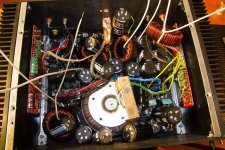
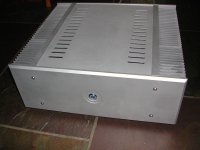
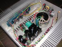
This is my Aleph 3. Modushop, 600VA 1,1F CLC PS. 21kg total
After 4th remake attempt it got a little bit messy so I hope this is final structure :]
After 4th remake attempt it got a little bit messy so I hope this is final structure :]
Attachments
Boy,
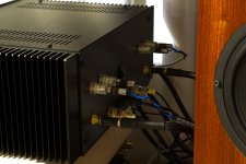
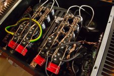
you need to twist more of your wiring pairs.
Have a look at the aerial loop in the Signal wiring at the RCA sockets.
You must reduce that loop area considerably.
Hi Andrew: I'm not sure I'm following you here....what can I do differently at the RCA sockets?
Hello together,
Please, see next answer (last sentence).
I don't know how much it is, Alex said it to me but i don't remember.
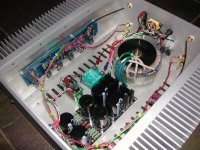
So, i asked Alex via mail and wait for a respond. Some other pics from Alex.
Wow that is HUGE!!! too bad the blades of the heat sink are horizontally, I think it will dissipate heat faster and easier if the blades are vertically.
Hi Andrew: I'm not sure I'm following you here....what can I do differently at the RCA sockets?
its fine
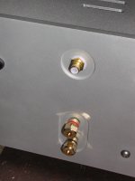
Im more worried that the long brass connectors could touch each other if one accidentally loosens and turn
very nice clean amp
Have a look at the aerial loop in the Signal wiring at the RCA sockets.
You must reduce that loop area considerably.
He is using shielded wire and it goes directly to the inputs of the amp PCB...
I'm not entirely sure how it could be made shorter... Am I missing something?
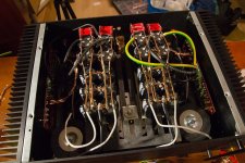
My F4.....it's been done awhile, just got around to snapping a few pics.
Very nice job! I think AndrewT is saying the RCA terminal are a little wider open than it should be. I do not think that is too much to worry about, as long as amp does not have any "back noise" all should be fine! I always use triple shielded microphone wire to connect the inputs and I have not encounter any problems with any back noise. so far..so good!
not that.Andrew, Is this what you are calling a loop? Through the negative/ground?
Look at the back of the RCA socket.
The shield is connected via a wire that is then soldered to the solder tag.
Look at the gap between the Signal wire and the grounding wire.
That gap is a loop. It picks up interference.
The loop can be made at least ten times smaller in area and with care maybe even reduced to 1% of the existing area.
Bare a tiny bit of signal and insert such that the screen nearly touches the free end of the RCA. Solder the signal to it's receptacle. Solder the screen to the end of the RCA using a tiny length of strand from a multi-strand core. If you are really careful you could try to solder 4 strands around the end of the RCA stub arranged at 90°. These extra strands contact the screen around the periphery of the screen.
Until I read Ott, I had not realised how important the complete circumference of the screen is to making the screening effective.
Ott repeatedly tells us to NOT use a screen pigtail.
Last edited:
Hi AndrewT are you talking about this in the "coaxial cable"?Extron Electronics - Answer: Hum, Buzz, and Ground Loops
Nice and clean boy, where did you get that chassis.
Duder: I built it using HeatsinkUSA 10.80" heat sinks, and aluminum angle and plate from a local metal supply house.
I should have added that the screen should extend all the way to the connector.
Hi Andrew: The screen/braid is tinned and soldered to the ground tab (no lead wire), but I suppose that I can make that entire joint a smaller "loop".
- Home
- Amplifiers
- Pass Labs
- Pictures of your diy Pass amplifier