Thanks everybody!
@Massimo: white boards are from forum member Teabag.
Heatsinks: https://www.distrelec.nl/elfa3~nl_nl/elfa/init.do?item=75-641-31&hst=4
Please don't buy them all
I used 4 of those for this build.
@Massimo: white boards are from forum member Teabag.
Heatsinks: https://www.distrelec.nl/elfa3~nl_nl/elfa/init.do?item=75-641-31&hst=4
Please don't buy them all
I used 4 of those for this build.
The MOSFETs are biased at 1.25 A each at 33.2 volts. Max temp on the heatsinks of 52.3 degrees Celsius.
Funny thing, your heatsink in 200mm height, would go up ~34C for 166W dissipation. (according to the datasheet)
At 25C ambient, close to 6OC heatsink temperature.
And only provided that the C/W number need not be corrected for operating at dT above ambient.
Your numbers suggest that the overlapping way you attached the square framework bars to the heatsinks, draws some serious heat away from the primary coolers. (aka rather interesting)
Definitely the looks of a couple of hundred hours of sweating.

Only pancakes for you, the schmokes are already there.
Hi Jacco,
Your calculation is right, you just assumed my Tamb is 25C, but hey at this moment it is 18.7C in my shack.
Thanks to the fact we haven't seen the sun here in Utrecht since the beginning of 2013 The worst spring ever....
Even in my livingroom it's barely 20C.
But I must say the heatsinks really starts to dissipate above 50C, even when pulling 400 watt from the mains, they were still below 60C, don't know the exact numbers, I was too busy shutting the amp down
Your calculation is right, you just assumed my Tamb is 25C, but hey at this moment it is 18.7C in my shack.
Thanks to the fact we haven't seen the sun here in Utrecht since the beginning of 2013
The worst spring ever....Even in my livingroom it's barely 20C.
But I must say the heatsinks really starts to dissipate above 50C, even when pulling 400 watt from the mains, they were still below 60C, don't know the exact numbers, I was too busy shutting the amp down
Last edited:
but hey at this moment it is 18.7C in my shack.
Brrrr, your Swiss side, I suppose ?
(really good heatsinks, though. ~1 dm3/W/C )
Last edited:
Nice built - no much unnecessary space in there
Regards
Sven
I've been measuring this and it concerns me... when the amp is around 53C the outputs are around 70C, I even measured 71,2C as max
On average I would say the housings of the MOSFET are around 15 degrees hotter than the heatsink... seems a lot...maybe my mica / silicone paste combi isn't that good.
Though I already splitted the mica insulators twice. So four times thinner than original.
The diodes under the transformers are around 45C, so that's OK.
Last edited:
I've been measuring this and it concerns me... when the amp is around 53C the outputs are around 70C, I even measured 71,2C as max
On average I would say the housings of the MOSFET are around 15 degrees hotter than the heatsink... seems a lot...maybe my mica / silicone paste combi isn't that good.
Though I already splitted the mica insulators twice. So four times thinner than original.
The diodes under the transformers are around 45C, so that's OK.
Hi Walter,
First of all congratulations on a really fantastic build.
As I've working for some months on something very similar and have tested exactly the closed box working temp of the Transistors i have to say...in chorus with master ZM
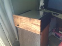
that the first thing that struck me was the small vents top and bottom.They are in principle not wide enough to permit proper airflow from bottom to top inside the case.
This case topology creats a "tunnel effect" as Patricks calls it because air coming in from bottom of case is directed in font of transistors ( main PCB ) before exiting through top, so wider entrance at bottom and exit at top would probably work better.
ZMs suggestion, already seen here in other great builds would be your easiest fix.
At least easy to try without any panel reworking.
Enjoy a really great build.
> On average I would say the housings of the MOSFET are around 15 degrees hotter than the heatsink...
> seems a lot...maybe my mica / silicone paste combi isn't that good.
This is a figure which would not surprise me for mica & grease.
I generally can get my MOSFET case to be within 5°C of the heatsink temperature measured next to the FET.
For more details you can download my article on thermal design of Class A amplifiers at Linear Audio (free).
All these issues were analysed in detail in the article.
http://www.linearaudio.net/images/stories/Didden LA V3 PK lr.pdf
The tunnel effect CeeVee mentioned will only help to lower temperature inside the case between the heatsinks (i.e. your transformer and caps).
It will not solve your MOSFET temperature issue.
If there would be one quick cure then buy some Kerafol from Conrad to replace the mica & grease.
My 2 cents,
Patrick
Last edited:
Hi Walter,
exactly the closed box working temp of the Transistors i have to say...in chorus with master ZM
ZMs suggestion, already seen here in other great builds would be your easiest fix.
At least easy to try without any panel reworking.
Enjoy a really great build.
Thanks CeeVee for the kind words, I will putt spacers between the top lid and chassis. Also for the bottom plate which is a bit harder to do, but thanks to my floating PSU, must be possible.
So you and master ZM
think 71C is acceptable ?Thanks Patrick! That excellent article is already in 'my Documents'
But I'm going to try the Kerafol, and figure out to clamp the FETs, cause I understood the Kerafols perform best under pressure.
The 5 degrees delta you mention sounds a lot better. Just for peace of mind.
I already ordered 16 new matched MOSFET from NicMac from the F5X GB and populate my amp boards with these. So that each MOSFET dissipates around 20 Watts instead of 40 Watt.
My v2 turns into a light v3
Thermal tracking must be improved with the NTC's, I want to build thermal protection on the amp, so that it switches off when sinks get hotter than 60C.
Anti hum must be implemented... So lot of nice work to come
Walter
> Thermal tracking must be improved with the NTC's,
If you are referring to those in the First Watt F5 circuit to bias the MOSFETs, then I don't use them.
I rather use a lower bias at room temperature. But that is my personal choice.
> I want to build thermal protection on the amp, so that it switches off when sinks get hotter than 60C.
You just need to add a thermal switch on series with the power supply.
I would use 75°C directly at the MOSFET case.
Measuring somehwere on a heatsink is not really reliable.
But you will, like me, realise that thermal protection is probably not necessary.
You can just put an ammeter to measure the current, or use a current limit on you power supply (not on the F5 circuit).
It is a much better protection for the FETs.
Again, my 2 cents,
Patrick
... think 71C is acceptable ?
No I'm sure 71ºC will go down.
Although Patrick is more precise...as always
...heat transfer efficiency from transistor case to heatsink might be an issue still.I use mica and goop with great results but Kerafol is better and easier solution...if you can get it.
This is a very demanding amp in terms of thermal management so it is worthwhile to optimize from source on...ie: transistor case on... definitely listen to Patrick
As a sure fire safety measure...make a ZM babysitter...i have one and it sure helps in Lisbon summer.
Moving just a little air works wonders....
Last edited:
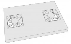
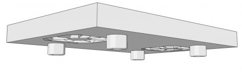
If you want the most gain in temperature reduction then use a slow blowing fan.
Works magic.
Patrick
That's what i call the ZM babysitter....Patrick.
With fans running at half rated voltage...noiseless!
Attachments
- Home
- Amplifiers
- Pass Labs
- Pictures of your diy Pass amplifier