nice build1
question from me to. why fan at the top?
stig
Heat rises.
Nice!
No diodes D1-D4?
How many VA is the power transformer?
You mean the MUR3020? They are all soldiers in pcbs, I removed the heatsinks because MUR3020 not warm, they are cold.
The toroidal 800VA 2X24V.
Nice. Two questions -- how did you do the lettering on the front, and where did you get the nice silver feet?
With lettering guide and a bookmark, the feet are solid aluminum, bought 4 pieces cut.
Blink_PT,
Can you give some info on your power supply design? I'm new to that part of DIYing and yours certainly appears interesting.
It is equal to the original F5T V2. Just follow the layout and soldering parts.
Heat rises.
I did some experiments, I put a fan behind the air out, but not works very well.
On top extracting the air temperature decreases.
Someone must have changed the picture!
Checked if your wallet's still in the back seat position ?
Checked if your wallet's still in the back seat position ?
I do not understand what you're saying!
I did some experiments, I put a fan behind the air out, but not works very well.
On top extracting the air temperature decreases.
let me see if I got this right.
1. fan mounted in back of the amplifier, blowing air into the amp
2. fan mounted on top of the amplifier, blowing air out of the amp

let me see if I got this right.
1. fan mounted in back of the amplifier, blowing air into the amp
2. fan mounted on top of the amplifier, blowing air out of the amp
Wrong.
At the rear has no fan. Just got the grill.
On top the fan is to extract air out.
Wrong.
At the rear has no fan. Just got the grill.
On top the fan is to extract air out.
but you tried it in the back? blowing air in? or sucking out? and this was not so good as on top sucking out air?
A fan or pump always works more effectively "blowing" the fluid.
A fan in the bottom of a case blowing up will perform better than a fan mounted on the top sucking up.
You just have to be sure not to turn your equipment into a vacuum cleaner
D.
Blink_PT,
How did you fix the PSU capacitors to the bottom of the cabinet ?
Thanks,
D.
They are based on a bakelite isolator plate with duct tape, double-sided.
The copper plate has two holes (see in the picture), now with a plastic clamp, but it will take two nylon bolts.
Another F5 finished, my first power amp, be clement
Boards come from diyaudio store, component from my box ( capacitors and diode bridges) and mouser. matched fets from spencer.
The first step, components soldered, and first turn on. The heatsink was too small... too hot...
http://sdrv.ms/Yz6XET
hifi2000 chassis, with main components.
http://sdrv.ms/11xeniD
Psu in place temporarly, because a problem of buzz in the speakers, I put the transformer in the other side of the chassis, and change the input cable to a shielded one from selectronic.
http://sdrv.ms/11xes5P
http://sdrv.ms/11xeyuj
http://sdrv.ms/11xeyuj
Final place of the psu, the transformer is holded by a metal part from computer chassis, and linoleum to prevent from damage that can be cause by metal part (maybe replace for better later). Conrad doesn't supply part to hold the transformer...
The capacitors supports was made by a 3D printer of a friend.Made to measure
http://sdrv.ms/YMJaRf
The front power switch is the same as this one :
http://sdrv.ms/YMJvU2
Thank to nelson pass for this great amp, and thanks to all people that ask and respond to all technical questions that make this forum so rich in terms of knowledge.
ty
%$!&%#@!!!
Need CSI DIY
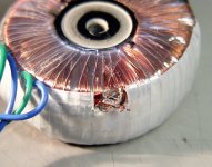
I probably know the answer, but is there any way to salvage a toroid?
You know the story - " I should remove that toroid in case the drill grabs and........ ". The outer three layers are cut or distorted.
Not expensive to replace but I thought I'd ask the question anyway. Isn't quite the picture I had planned to post this weekend.
Need CSI DIY
I probably know the answer, but is there any way to salvage a toroid?
You know the story - " I should remove that toroid in case the drill grabs and........
". The outer three layers are cut or distorted.Not expensive to replace but I thought I'd ask the question anyway. Isn't quite the picture I had planned to post this weekend.
Attachments
Drill out the core filling.
tape up the insulation both sides of the damage.
cut and remove the insulation to reveal the windings.
cut and count the turns that you remove. Try to just remove the outer layer/s.
If a deeper layer is damged then remove that as well.
You will have to be sure which windings you have exposed by measuring back to the original lead outs. Sometimes the manufacturer uses slightly different colours of enamel on the bi-fillar windings.
Now wind back on the required "patch" turns to repair each layer in turn.
Insulate the soldered joints very thoroughly.
Last edited:
- Home
- Amplifiers
- Pass Labs
- Pictures of your diy Pass amplifier