in that case - be sure that either screw is electrically isolated on one ( even better - both ) ends ..... or that your screen-bell is electrically isolated from bottom of case , so you are not having shorting turn through donut itself
wire in windings is also isolated from core , electrically ..... but not magnetically
wire in windings is also isolated from core , electrically ..... but not magnetically
Attachments
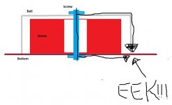
I like the EEK!
I'd wait to say that till I was absolutely positive what it means in Serbian.
(Eek me, Z)
without the right tools
A piece of pipe can be bought by the cm/inch.
The lid can be made with a generic electric drill, a metal file, and patience.
Leaves the acetylene & oxygen bottles, and a lighter.
I'd wait to say that till I was absolutely positive what it means in Serbian.
(Eek me, Z)
Uh good point.
Toroid shield
Another option, to preserve the clean looks of the shield. Use a good silicone to bond the shield over/around the transformer. Silver solder a piece of wire or braid to the bottom edge of the shield, and run it to a good chassis ground (or just let the shield "float", ungrounded, if hum is not a problem). Result is a grounded shield, with no bolts/nuts showing in the top, and with no dreaded "magnetic loop" around the toroid core. Voila.
(Now, back to the "photos" in this Pass amp photo thread!..... )
)
Hmm... I didn't know that there still are possibilities for the electrical loop when trafo center is "metal free", but now that you say it makes sense with the magnetism and all. Well I have to make myself a nylon bolt then.
Another option, to preserve the clean looks of the shield. Use a good silicone to bond the shield over/around the transformer. Silver solder a piece of wire or braid to the bottom edge of the shield, and run it to a good chassis ground (or just let the shield "float", ungrounded, if hum is not a problem). Result is a grounded shield, with no bolts/nuts showing in the top, and with no dreaded "magnetic loop" around the toroid core. Voila.
(Now, back to the "photos" in this Pass amp photo thread!.....
)Great work on the cover! Would the value of such a cover be to reduce stray fields or the transformer's mechanical noise?
The transformer that I bought is designed for audio applications and have a minimal magnetic leakage so the cover is probably not necessary. I made it because the inside of the amp will be more "clean" looking in my opinion. If it also shields the trafo a little I consider that a bonus.
I'm with you 100%. It does look great and worth the effort on that basis alone. I was just curious because it looks tough to have so many diverse elements in a case without interference. I wondered if some level of scrutiny for their physical arrangement wasn't worthwhile. Then... I was thinking way back to my EE transmission line lab and our measured results for line-of-sight, ungrounded shields were not very good. Someone here may have some real emag experience to refute my observation but maybe an insulated cover would be mainly cosmetic? but hey, from a guy that buys chrome valve covers... i still like it
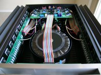
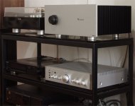
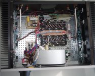
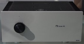
F5T V2
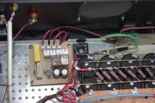
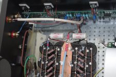
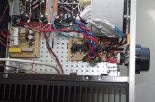
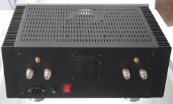
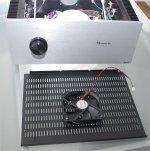
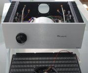
Finally everything is finalized.
It has a bridge rectifier for the two channels as the original.
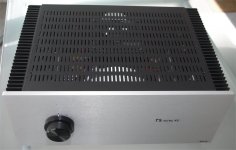
Built a soft start and a low noise fan at the top.
All tuned, and now it's just music.
Finally everything is finalized.
It has a bridge rectifier for the two channels as the original.
Built a soft start and a low noise fan at the top.
All tuned, and now it's just music.
Attachments
-
 F5TQ.jpg129.4 KB · Views: 713
 -
 F5TO.jpg232.2 KB · Views: 740
 -
 F5TN.jpg190.9 KB · Views: 624
 -
 F5TM.jpg182.4 KB · Views: 642
 -
 F5TH.jpg165.7 KB · Views: 1,199
 -
 F5TK.jpg115 KB · Views: 1,222
 -
 F5TI.jpg201.5 KB · Views: 1,294
 -
 F5TG.jpg148.4 KB · Views: 1,333
 -
 F5Td.jpg80.2 KB · Views: 1,375
 -
 F5TJ.jpg118.1 KB · Views: 481
No diodes D1-D4?
Are they mounted away from the heatsink?
- Home
- Amplifiers
- Pass Labs
- Pictures of your diy Pass amplifier